6
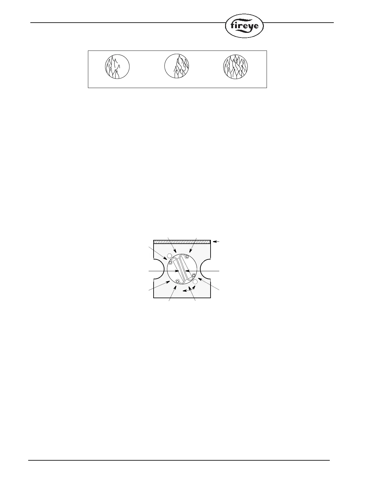
FIGURE 4. FLAME MUST COMPLETELY COVER SIGHT OPENING
7.
The scanner viewing window must be kept free of contaminants (oil, ash, soot, dirt) and the scan-
ner temperature must not exceed the maximum rating. Both requirements will be satisfied by con-
tinuous injection of air at either the 3/4" housing inlet or at a 1" wye ahead of the swivel mount, as
shown in Figure 6.
Purge air may be supplied through the 3/4" or 1" wye connection. Normally only one of the two
connections is provided with purge air and the other connection is plugged. When a Fireye sealing
coupling is used as shown in Figure 6, the 1" wye connection is used for the purge air (plug
3/4" opening).
Under normal conditions, with clean burning fuels and moderate ambient temperature conditions,
purge air flow of approximately 4 SCFM (113 L/min.) @ 4" water column above furnace pressure
is generally adequate. Up to 15 SCFM (425 L/min.) may be required for fuels that may produce
high levels of flash or soot or for hot environments to maintain scanner internal temperature within
specification.
FIGURE 5. UV TUBE POSITION
Note: To change UV Tube position, pull tube out and rotate to desired position. Then insert.
8. Excessive flame signal can affect flame discrimination and prevent the control connected to the
scanner from performing properly. Weak signals may cause unnecessary burner shutdown or
alarms. To change the signal level of the tube, remove the UV tube, rotate it, and replace it in the
eight pin (octal) socket.
The tube has four different significant positions as shown in Figure 5. When the electrodes are
almost perpendicular to the Terminal Board and approximately parallel to the shutter slot, the
detector tube will generate maximum signal. This is the “Maximum Position” shown in Figure 5.
When the electrodes are 90 from the maximum position, minimum signal will be generated. The
intermediate positions, “A and B” (as indicated in Figure 5) will yield intermediate signals. Posi-
tion “A” will yield a slightly higher signal than the intermediate position “B” since more electrode
will be exposed to the radiation entering the shutter slot. To adjust the signal intensity further, use
the appropriate sensitivity adjustment in the control unit selected for use with this scanner. Refer
to the appropriate control bulletin for further information. The detector is positioned in the max-
imum signal orientation at the factory.
BUT THISNOT THIS NOT THIS
()
()
()
()
B
MAX
MAX B
A
A
ELECTRODES
TERMINAL BOARD
UV TUBE
SHUTTER
SLOT
RECTANGULAR