7
If the tube position is changed in the field, and the scanner is later replaced, verify that the signal
strength is not excessive.
9. The scanner sight pipe should be as large as is practical. Ideally, the sight pipe should increase
one inch in diameter (ID) for every foot in length. Under most circumstances, a sight pipe diam-
eter increase of one inch should be adequate for an increase in length of three feet (1m). When
applying the scanner to long sight tubes (more than three feet), minimize the use of one inch
pipe. Avoid using pipe less than one inch (ID), and avoid using stainless steel sight pipes.
10. Where separate scanners are used to monitor main and igniter flames, the main flame scanner
should be sighted to not detect the igniter flame. If it does detect the igniter flame, re-aim the
main flame scanner.
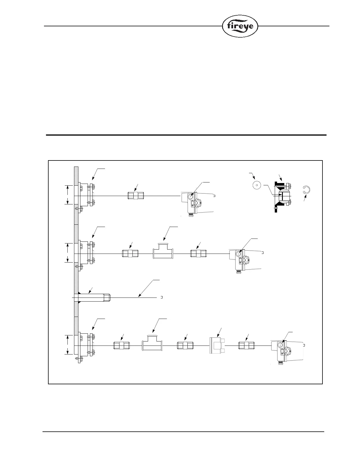
PIPING ARRANGEMENTS
FIGURE 6.
0 70
0 70
#60-1664
1” SWIVEL MOUNT
#35-127
HEAT INSULATING NIPPLE
STANDARD MOUNTING
#60-1664
1” SWIVEL MOUNT
#35-127
HEAT INSULATING NIPPLE
MOUNTING FOR
HIGH TEMP.
APPLICATIONS
3/4” PLUG
(BACKSIDE)
COOLING AIR/ENTRY
(PURGE AND COOLING)
#35-127
HEAT INSULATING NIPPLE
1” SIGHT PIPE
(BY OTHERS)
3/4” AIR ENTRY
(PURGE AND COOLING)
(BACKSIDE)
ALTERNATE STANDARD MOUNTING
(NOT ADJUSTABLE)
0 70
#60-1664
1” SWIVEL MOUNT
#35-127
HEAT INSULATING NIPPLE
MOUNTING FOR SPECIAL
APPLICATIONS - HIGH PRESSURE
3/4” PLUG
(BACKSIDE)
#35-127
HEAT INSULATING NIPPLE
#35-127
HEAT INSULATING NIPPLE
#60-1199
SEALING UNION WITH QUARTZ
WINDOW. REQUIRED WHEN SCANNER LENS
IS EXPOSED TO EXCESSIVE PRESSURE
FURNACE OR WINDBOX PRESSURE
APERTURE
#53-121
#60-1664
1” SWIVEL MOUNT
RETAINER
#34-181
COOLING AIR/ENTRY
(PURGE AND COOLING)
TEE PIECE (BY OTHERS)
TEE PIECE (BY OTHERS)
A
B
D
C
REFER TO THE FOLLOWING PAGES FOR AVAILABLE PART NUMBERS
3/4” AIR ENTRY
(PURGE AND COOLING)
(BACKSIDE)