9
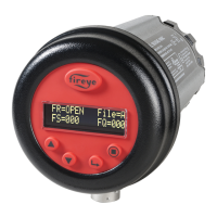
FIGURE 7.
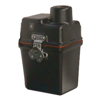
FIGURE 8.
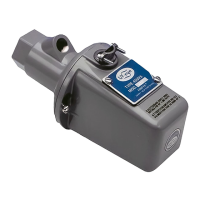
FIGURE 9.
ACCESSORIES
Swivel Mount
The scanner swivel mount (P/N 60-1664-3, -4) is used to adjust the scanner sighting angle after the
scanner has been installed. The swivel mount is used as indicated in Figure 6.
Orifices
The orifice is used to restrict field of view (target area), reduce air flow, maintain air block, and
increase discrimination between flame and background radiation. The orifice is secured within the
ball of a swivel mount with an orifice retainer or the orifice can be placed within a 1 inch coupling
(not provided).
The scanner should ideally sight a target area of 4 to 25 square inches (25-250cm
2
) of the flame
front. The flame front is a plane within the combustion space separating the region of unburned fuel
from the burning fuel. For example, if a 1/2 inch diameter orifice is placed within a mounting swivel
one foot from the scanner lens, and the swivel mount is located on the surface of a 4 foot deep wind-
box, and if the range of stable flame is 5 feet beyond the windbox, the flame front target area is 19.6
square inches as shown in Figure 10.
A.Tube 4-320-1
B.Shutter 61-7181-1
B
A
A-I. Orifices: 0.062" - 0.5" DIA
J. Orifice Retainer 34-181
K. Heat Insulating Nipple 35-127-1 (NPT)
Heat Insulating Nipple 35-127-3 (BSP)
L Diode 101-78
M. Sealing Quartz Window 92-48
N. Quartz Scanner Lens 002611-001
Lens O-Ring (Not Shown) 2 needed 107427-006
Lens Retainer Ring (not shown) 101537-001
L
N
A. Swivel Mount 60-1664-3 (NPT)
Swivel Mount 60-1664-4 (BSP)
B. Sealing Coupling with Quartz Window
60-1199-1 (NPT), 60-1199-2 (BSP)
AB
 Loading...