HEIGHT ADJUSTABLE RETURN FRAME KIT
ASSEMBLY INSTRUCTIONS
RANGE
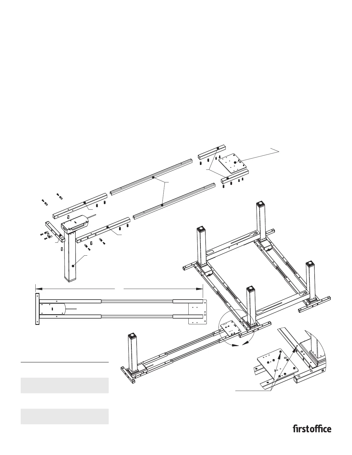
1. Attach cross tubes A & B and strut tube to leg column by
inserting the plastic screw guides into the mounting holes
and securing with (2) m6x15 machine screws per tube.
2. Insert spanner bars into end tubes minimum 3.75" with
notch facing downward and secure with m10x25 set crews.
(Adjust depth of spanner bars as needed for shorter length
return tops.)
3. Attach mount plate to the end tubes using m6x15 machine
screws. (If the main work surface is a hart item # use hole set
A and if the main work surface is a hart item # use hole set B)
4. Attach return frame assembly to the bench kit assembly
aligning holes in the mount plate with holes in the cross
tube & secure with (3) m6x15 screws. Mount plate will be
mounted letter side down for LH returns and letter side
up for RH returns.
INSTRUCTION SHEET #2573INS
PART #1730530
TOP SIZES XX
24"D WORKSURFACE
+
42" RETURN TOP
42"
24"D WORKSURFACE
+
48" RETURN TOP
48"
30"D WOR
KSURFACE
+ 42" RETURN TOP
48"
30"D WORKSURFACE
+
48" RETURN TOP
54"
CROSS TUBE A
CROSS TUBE B
ASSEMBLED LENGTH
A
A
XX
SPANNER BARS
MOUNTING PLATE
NOTE: MOUNTING
POSITION FOR
LH OR RH RETURN
IN STEP 4 BELOW
STRUT TUBE
HEIGHT ADJUSTABLE
LEG COLUMN
ALIGN HOLES IN MOUNT PLATE
WITH HOLES IN CROSS TUBES
& ATTACH USING (3) M6X15
MACHINE SCREWS