4
MOUNTING SPACE WALL CONSTRUCTION
Please read all instructions thoroughly before installing the Over-the-range microwave oven.
Two people are recommended to install this product.
If a new electrical outlet is required this must be completed by a qualified electrician
before the Over-the-range microwave oven is installed. See ELECTRICAL GROUNDING
INSTRUCTIONS.
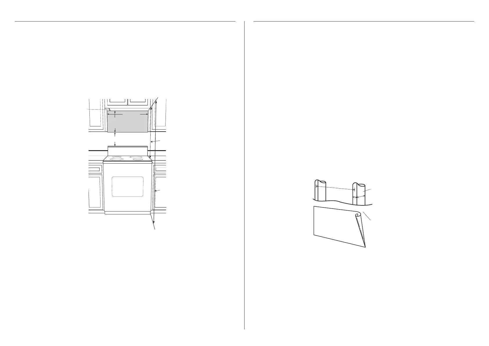
This Over-the-range microwave oven requires a mounting space on a wall as shown in Figure 1.
For proper installation and servicing, a 2 in/51 mm space is necessary between the top of the
range backsplash and the bottom of the Over-the-range microwave oven.
Backsplash
Min. 30"
(762 mm)
At least 2" (50.8 mm)
16.3"
(414 mm)
66" (1676.4 mm)
30" (762 mm)
or more from
cookingsurface
Min. 12" (304.8 mm)
Figure 1
This Over-the-range microwave oven should be mounted against and supported by a flat
vertical wall. The wall must be flat for proper installation. If the wall is not flat, use spacers to
fill in the gaps.
Wall construction should be a minimum of 2 in x 4 in (51 mm x 102 mm) wood studding and
3
⁄8 in (10 mm) or more thick dry wall or plaster/lath. The mounting surfaces must be capable
of supporting weight of 110 lb (50 kg)—the oven and contents and the weight of all items
which would normally be stored in the top cabinet above the unit.
The unit should be attached to a minimum of one 2 in x 4 in (51 mm x 102 mm) wall stud.
To find the location of the studs, one of the following methods may be used:
A. Use a stud finder, a magnetic device which locates the nails in the stud.
B. Use a hammer to tap lightly across the mounting surface to find a solid sound. This will
indicate stud location.
The center of the stud can be located by probing the wall with a small nail to find the edges
of the stud and then placing a mark halfway between the edges. The center of any adjacent
studs will normally be 16 in (406.4 mm) or 24 in (610 mm) to either side of this mark.
If the unit is unable to be supported by a stud, toggle bolts and top cabinet screws will need
to be placed, see details in the
WALL TEMPLATE. The top cabinet should be tested to ensure it
is securely attached to the wall. Place extra weight up to 110 lb (50 kg) inside the top cabinet
to test the support.
2"x 4"
(51 mm x 102 mm)
wood studs
3/8" (10 mm)
dry wall or
plaster/lath
16" (381 mm) or 24" (9610 mm)
Figure 2

 Loading...