Do you have a question about the Fisher & Paykel DE40F56AW1 and is the answer not in the manual?
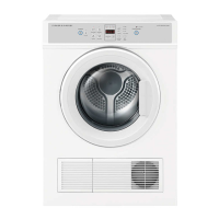
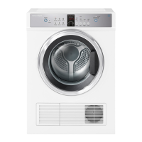
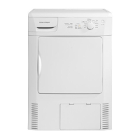
Details of dryer models, features, and finish.
Physical dimensions of the dryer units.
Packaging dimensions for DE40F56 models.
Packaging dimensions for DE50F56 models.
Information on vent hose length and allowances.
Specifies the vent diameter for DE50F56 models.
Specifies the maximum load capacity in kg for models.
Dry weight and packed weight details for models.
Weight specifications for DE40F56 models.
Weight specifications for DE50F56 models.
Electrical ratings, power, and current details.
Details on the dryer's power cord type and specifications.
Information about the motor type and specifications.
Specific details on the Fasco motor used.
Specific details on the WITC motor used.
Specifications for the heating element.
Heating element specs for specific models.
Heating element specs for DE50F56EW model.
Operating temperatures for the thermostat.
Resistance values for the exhaust sensor.
Material specification for the dryer cabinet.
Details on the dryer drum construction.
Drum material, volume, speed, and airflow.
Drum material, volume, speed, and airflow.
Drum material, volume, speed, and airflow.
Explains how a vented dryer operates, air flow, and heating.
Describes drum drive mechanism, belt, and mounting.
Details on temperature measurement components.
Specifics on thermostat operation and trip points.
Location and function of the exhaust sensor.
Description of the heating element and its control.
Explanation of the mechanical door locking mechanism.
Function of the door switch in different models.
Door switch connection for analogue models.
Door switch connection for electronic models.
Role of the electronic control module.
Details about the motor type and capacitor.
Procedures for testing the dryer motor.
Methods to test motor resistance at the panel.
Specific test for DE50F56AW1 motor at control panel.
Specific test for DE50F56A2 motor at control panel.
Specific test for DE50F56EW motor at control panel.
Procedures for testing motor resistance directly at the motor.
Testing various components via control panel.
Testing NTC sensor resistance.
Testing DE50F56EW door switch.
Testing door switch for analogue models.
Testing door switch for push-to-start models.
Testing heater/thermostat circuit for DE50F56EW.
Testing heater/thermostat for analogue models.
Testing heater/thermostat for push-to-start models.
Steps to remove the timer knob.
Instructions for removing the control panel.
Steps to remove the top panel of the dryer.
Procedure to remove the rear panel.
Detailed steps for removing the dryer drum.
Guide to replacing front drum bearings.
Guide to replacing front drum bearings.
Instructions for replacing the rear drum bearing.
Steps for removing specific components.
Procedure to remove the fan from DE40F56.
Steps for removing the main motor.
Procedure to remove the fan from DE50F56.
Steps to remove the motor's drive pulley.
Instructions for removing jockey pulley.
Instructions for removing jockey pulley.
Steps to remove the timer mechanism.
Procedure for removing the electronic controller.
Steps to detach and remove the dryer door assembly.
Procedure to remove the door switch.
Procedure to remove the door switch.
List of tools required for disassembly.
Procedure to test LEDs and buttons on the control panel.
Test for drum movement and heating element function.
Tests to verify exhaust sensor and door switch operation.
Explanation of fault codes and display patterns.
Diagnosis and action for faulty exhaust sensor.
Fault code for sensor shorted to cabinet.
Faults related to exhaust or ambient sensors.
Fault condition for high exhaust air temperature.
Fault code indicating power supply instability.
General category for other PCB-related faults.
Wiring diagram for electronic dryer model.
Wiring diagram for analogue dryer model.
Wiring diagram for analogue dryer model.
Wiring diagram for analogue dryer model.
Wiring diagram for analogue dryer model.
Sequence chart for analogue models.
Sequence chart for push-to-start models.
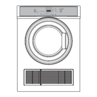
This document provides a comprehensive service manual for Fisher & Paykel compact dryers, covering models DE40F56AW1, DE50F56AW1, DE50F56EW1, DE40F56A2, and DE50F56A2. It details the principles of operation, component descriptions, testing procedures, disassembly instructions, fault modes, wiring diagrams, and common drying problems.
The compact dryer operates as a vented system. Ambient air is drawn into the cabinet by a fan attached to the motor. This air is then pressurized and forced over a heating element, where it is heated. The heated air enters the drum from the rear, interacting with the clothes to facilitate drying. The humid hot air then exits the dryer through the lint filter and an exhaust duct.
The dryer's mechanical system includes a main motor, which is secured by two spring clips to motor brackets. A poly-v belt connects the motor pulley to the drum, driving its rotation. The drum itself is constructed from pre-painted or stainless sheet steel. It is mounted into a front bearing housing, while the rear bearing is fixed to the inside rear of the drum by screws and attached to the heater plate. The heater plate, in turn, is held by two brackets mounted to the wrapper.
Temperature regulation is managed by two thermostats, both located and mounted on the heater plate. These thermostats monitor heater temperatures and control the heater's on/off cycles. They are designed to trip open at 73°C +/- 3°C and close at 58°C +/- 5°C. For the DE50F56EW model, an additional exhaust sensor (NTC) is located in the exhaust duct to monitor exhaust temperature.
The heating element is a 1750-watt, 2-circuit or 1-circuit tubular stainless steel component. In analogue models, it is driven by a timer, while in electronic dryers, two relays energize the elements after the motor has started.
A mechanical door lock mechanism ensures the door remains shut during operation. When the door is pushed closed, a strike engages with a catch. The door micro switch plays a crucial role in safety and operation. In DE40F56AW and DE50F56AW models, the main power's active line connects to the door switch and then to the timer control. Opening the door opens the contacts, cutting the active supply to the timer, motor, and heater. For the DE50F56EW model, the door switch connects to the electronic control module. When closed, it allows the start/pause button to activate the motor and heater. Opening the door stops the controller from driving the motor or heater.
The DE50F56EW model features an electronic module that controls the main motor's constant speed, manages program steps, reads NTC temperatures, and activates or deactivates the heater. The main motor is a single-phase permanent split capacitor motor, operating at approximately 1400 rpm and equipped with a 7uF run capacitor. In DE50F56EW models, relays control the motor and reverse drum direction, while in DE50F56AW models, the timer controls drum direction reversal. The DE40F56AW model operates in a single direction without reversal.
The manual outlines program steps and component testing procedures for various parts of the dryer. For motor testing, measurements can be taken at the control panel or directly at the motor, with specific resistance values provided for different models and motor types. NTC, door switch, heater, and thermostat testing can also be performed at the control panel, with detailed instructions for resistance measurements in different states (e.g., door closed/open, specific temperatures).
The service manual provides detailed disassembly procedures for various components, including the timer knob, control panel, top panel, rear panel, drum, front and rear drum bearings, bearing holder, air duct assembly, felt seal, fan, motor, motor driving pulley, jockey pulley, electronic controller, and door assembly. Each procedure includes step-by-step instructions for removal and reassembly, often with important notes regarding alignment, screw types, and handling precautions. For instance, when reassembling the drum, it's crucial to ensure the drum belt is correctly positioned, and the felt seal is checked. When replacing drum bearings, the surface on the front edge of the drum must be free from grease and rough surfaces.
The manual also covers electronic module connection checks, including LED and button tests, drum rotation and element checks, and exhaust sensor and door switch tests. These tests help verify the correct wiring and operation of the electronic module.
Fault modes are extensively described, with specific fault codes displayed on the Dryness LEDs accompanied by a continuous buzzer sound. These codes help diagnose issues such as faulty exhaust sensors (open circuit, shorted to cabinet), faulty exhaust or ambient sensors, and over-temperature conditions. Each fault code is accompanied by an action to troubleshoot and resolve the issue, such as checking sensor resistance or inspecting the lint filter and exhaust duct for blockages. A "Brown Out" fault code indicates a drop in supply voltage below 180 volts, which can be resolved by restarting the dryer.
Instructions for testing the exhaust sensor involve measuring its resistance at normal room temperature (25°C) and 0°C, using a multi-meter. Door switch adjustment guidelines ensure the door switch activates the PAUSE mode within a specific opening range (40mm – 65mm).
Wiring diagrams are provided for electronic and analogue dryer models, illustrating the connections between various components. Finally, a section on common drying problems offers solutions for issues like creasing, lint transfer, tangling, uneven drying, stiff fabrics, and shrinkage, often attributing them to overloading, inappropriate sorting, blocked lint filters, or incorrect cycle selection.
| Brand | Fisher & Paykel |
|---|---|
| Model | DE40F56AW1 |
| Type | Vented Dryer |
| Width | 600 mm |
| Height | 850 mm |
| Color | White |