5
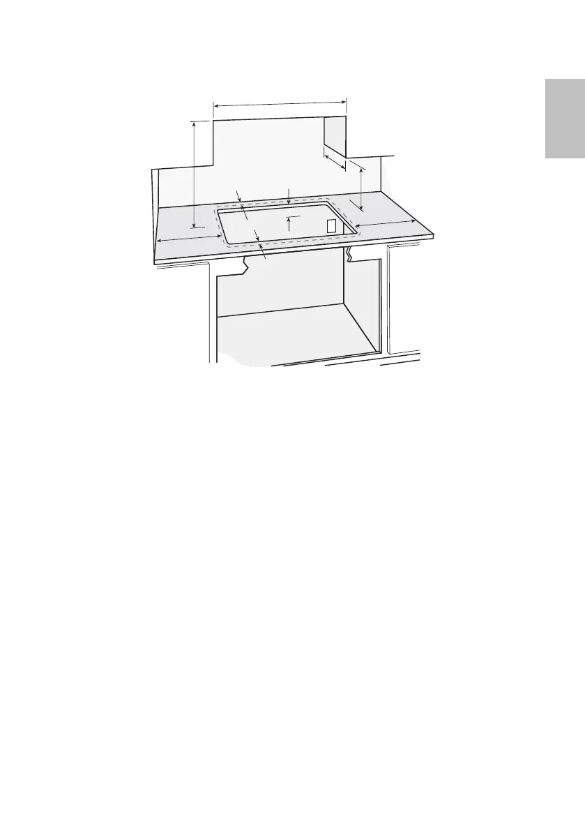
Clearances
a 36” = Minimum horizontal distance between overhead cabinets installed on either side of
this appliance.
b 30” = Minimum clearance from combustible surface centered above the cooktop.
c 13” = Maximum overall depth of overhead cabinetry.
d 18” = Minimum clearance from countertop to overhead cabinetry.
e 4” (GC36) or 1
1
/
2
” (GC912 & GC912M) = Minimum clearance from cooktop to the left side wall.
f 1” = Minimum clearance from cooktop to the right side wall.
g 1
1
/
2
” (GC36) or 1
1
/
4
” (GC912 & GC912M) = Minimum clearance from cooktop to the rear wall.
h 2
1
/
2
” (GC36) or 1
1
/
4
” (GC912 & GC912M) = Minimum distance from front edge of counter to
front edge of appliance. Where this reduces the distance between the back edge of the
appliance and the adjacent wall to less than the minimum of 1
1
/
2
” (GC36) or 1
1
/
4
” (GC912 &
GC912M), this wall must be of non combustible material (see note below).
i 2
3
/
8
” (GC36) or 3
5
/
16
” (GC912 & GC912M) = Minimum clearance below countertop to any
combustible surface.
j 30” = Maximum distance to nearest grounded power outlet from the center of the cooktop.
The power cord must not touch any hot metal surfaces.
Non-combustible material
Recommended non combustible materials are:
1
/
4
”” (6mm) flame retardant millboard covered
with not less than No. 28 MSG sheet steel, 0.015” (0.4mm) stainless steel, 0.024” (0.6mm)
aluminium or 0.020” (0.5mm) copper.
US
b
i
e
g
d
j
f
a
c
h

 Loading...