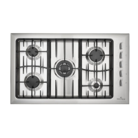
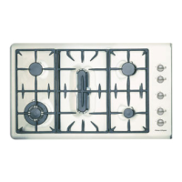
11
6.0 REPLACEMENT & SERVICING OF ELECTRONIC IGNITION
6.1 To Replace an Electrode
6.1.1 Disconnect from power.
6.1.2 Remove the product top panel - (see Section 4).
6.1.3 Unlatch the appropriate locating spring and remove the electrode. Replace
6.1.4 Reassemble in reverse order.
6.2 To Replace Ignition Box
6.2.1 Disconnect from power.
6.2.2 Remove the product top panel - (see Section 4).
6.2.3 Unplug the electrodes and the multiway plug from the ignition box.
6.2.4 Replace the box. the igntion box is held down by double sided foam tape.
6.2.5 For the auto reignition box.
Electrode wires must be plugged into correct terminals. Terminal Numbers on the ignition box
correspond to:
#1: Front left burner
#2: Front right burner
#3: Middle burner
#4: Rear left burner
#5: Rear right burner
6.2.6 Reassemble in reverse order.
6.3 To Replace the Microswitch Harness (GC901 Only)
6.3.1 Disconnect from power.
6.3.2 Remove the product top panel - (see Section 4).
6.3.3 Lift off microswitch assembly and replace.
6.3.4 Reassemble in reverse order.

 Loading...


