Do you have a question about the Fisher Scientific 10-550-126 and is the answer not in the manual?
Lists essential safety measures for operating the furnace, including personal protective equipment.
Highlights specific safety warnings regarding ceramic fibers and explosion hazards during setup.
Provides detailed instructions for replacing a defective heater element.
Guides the user through the process of replacing the temperature sensor.
A table correlating symptoms with probable causes and corrective actions.
Illustrates the internal electrical connections and component layout of the furnace.
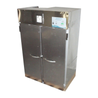
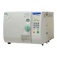
The Fisher Isotemp® Muffle Furnace 550 Series is a laboratory instrument designed for high-temperature applications, offering precise and reliable thermal processing. Available in small (Model 14), medium (Model 58), and large (Model 126) sizes, these furnaces are equipped with PID microprocessor temperature control, allowing for operation across a broad temperature range from 50 to 1125°C (90 to 2057°F).
The primary function of the Isotemp Muffle Furnace is to provide a controlled high-temperature environment for various laboratory processes, such as ashing, heat treating, and material testing. Its design prioritizes fast heat-up and cool-down times, achieved through the use of furnace chambers molded from alumina silicate ceramic fibers. This material also contributes to an unusually low exterior furnace temperature, enhancing safety during operation. Heating is accomplished by electric resistance elements embedded in easily removable side and base panels. These elements are engineered for extended service life, even when processing samples that produce challenging atmospheres, such as high-sulfur coal and coke.
Temperature monitoring and control are user-friendly, with a 7-segment display providing clear temperature readouts. A heater LED, positioned to the left of the temperature display, illuminates when the heating elements are actively energized. For applications requiring atmospheres other than air (e.g., N2, CO2), the furnace includes a 3/8-inch port for easy connection to external gas supplies. An optional Injection Port Kit (10-550P) can be connected to the exhaust port for convenient chamber venting.
Safety is a key aspect of the Isotemp furnace design. An automatic power cut-off to the heating elements is activated when the furnace door is opened, preventing accidental exposure to high temperatures. Additionally, a safety mechanism cuts heater power if the chamber temperature exceeds the set point by 100°C or more. In such an alarm condition, the display flashes "HIGH" to alert the user. A ventilated base design helps protect the bench or countertop from heat damage.
The furnace features a simple three-button control interface. Arrow keys allow users to increase or decrease the furnace temperature set point. A front panel Mode key enables toggling the display between the set point temperature and the actual furnace temperature.
Operating the Isotemp Muffle Furnace involves a straightforward process. Upon initial power-on, the display shows "Inlt" followed by the current furnace temperature in °C. To set a desired temperature, the user presses the Mode keypad, which displays the last setpoint. The UP or DOWN arrow keys are then used to adjust the setpoint. A decimal point illuminates when a change is made, and holding the arrow key allows for rapid adjustment. The new setpoint is confirmed by pressing the Mode keypad again or by waiting three seconds, after which the heater indicator LED will light, and the chamber will begin to heat.
The furnace also allows for a display offset to calibrate the temperature display and control point against a reference standard. This feature ensures that the temperature shown on the display accurately reflects the actual furnace temperature, accounting for any minor discrepancies. The display offset values can be adjusted within a range of ±30°C.
Important operational indicators include "otc" (open thermocouple), which appears if the thermocouple becomes detached or broken, causing the heaters to be held off. The "HIGH" alarm flashes if the chamber temperature exceeds the setpoint by 100°C, triggering the safety relay to cut the heater circuit. This alarm will clear once the temperature falls within 25°C of the setpoint, allowing normal heater control to resume.
When operating the furnace, several safety precautions must be observed: always wear insulating gloves, use tongs for handling items inside the hot chamber, wear safety goggles, and never stand directly in front of an open furnace. The supplied hearth plate must always be used on the chamber bottom. The furnace should be installed in a location that provides at least four square feet of space and is capable of supporting its weight (60lbs for Model 14, 90lbs for Model 58, 110lbs for Model 126). It should be within three feet of an appropriate power outlet, avoiding extension cords. It is crucial not to install the furnace closer than 6 inches to combustible materials. If toxic volatiles are expected from samples, the furnace should be placed in a fume hood or connected to an accessory Exhaust Tube Assembly for proper venting.
Maintenance of the Isotemp Muffle Furnace primarily involves replacing heaters and thermocouples, tasks that should only be performed by qualified personnel after disconnecting the power cord and allowing the chamber to cool to ambient temperature.
To replace a defective heater, the process involves:
Replacing a defective thermocouple involves:
Troubleshooting guidance is provided for common issues such as the furnace not powering up (check circuit breaker, power switch), controls operating outside the expected range (faulty solid-state relay, door switch issues, bad safety relay), heater LED on but no heat (setpoint too low, door switch malfunction, bad safety relay, faulty solid-state relay, defective heater elements), and "otc" error (open thermocouple connection). For issues beyond user-correctable problems, technical support should be contacted.
| Brand | Fisher Scientific |
|---|---|
| Model | 10-550-126 |
| Category | Laboratory Equipment |
| Language | English |