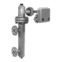
2502 Series
10
structions in the Calibration section to simulate the
process variable changes required for these checks.
Make sure that the raise level dial on the controller is
mounted with the correct side facing out. The dial is
printed on both sides with the arrow on one side point-
ing to the left and the arrow on the other side pointing
to the right. Figure 11 shows the dial arrow positioned
for a sensor that is mounted to the left of the control-
ler; the arrow points to the left. If the sensor is to the
right of the controller, remove the two mounting
screws, turn the dial over so the arrow points to the
right, then reinstall the mounting screws.
On a controller with optical mechanical indicator as-
sembly, the travel indicator plate is printed on both
sides. If the sensor is to the left of the controller (right-
hand mounting), use the side of the plate that has the
arrow pointing to the left. If displacer is to right of con-
troller (left-hand mounting), use the side of the plate
that has the arrow pointing to the right.
1. Turn on the supply pressure and check that the
controller supply gauge reads 20 psig (1.4 bar) for a 3
to 15 psig (0.2 to 1.0 bar) output pressure range or 35
psig (2.4 bar) for a 6 to 30 psig (0.4 to 2.0 bar) output
pressure range. If the pressure is incorrect, loosen the
locknut of the filter/regulator (figure 3); turn the adjust-
ing screw clockwise to increase or counterclockwise to
decrease pressure. Tighten the locknut after setting
the pressure.
2. Turn the reset control to .05 minutes per repeat.
3. Locate the process variable at its minimum value
(on level applications, for instance, lower the liquid
below the displacer). Zero the proportional band and
raise level controls. Output pressure on direct-acting
controllers should be greater than zero but less than 3
psig (0.2 bar) for the 3 to 15 psig (0.2 to 1.0 bar) range
or 6 psig (0.4 bar) for the 6 to 30 psig (0.4 to 2.0 bar)
range. For reverse-acting controllers, the output pres-
sure should be greater than 15 psig (1.0 bar) and less
than 20 psig (1.4 bar) for the 3 to 15 psig (0.2 to 1.0
bar) range or greater than 30 psig (2.0 bar) and less
than 35 psig (3.4 bar) for the 6 to 30 psig (0.4 to 2.0
bar) range. On a controller with indicator assembly,
the pointer should be over the low point on the indica-
tor plate; slight adjustment might be necessary by
loosening the bottom shaft nut (key 40, figure 16),
shifting the pointer, and retightening the nut.
4. Set the raise level control as desired. Determine
the dial setting by moving the nameplate slide until the
specific gravity on scale B is opposite the displacer
volume on scale A. Choose the percentage of displac-
er length, as measured from the displacer bottom, that
you desire the liquid or interface level to cover. Locate
this percentage on scale D, and read up from this per-
centage to find the raise level dial setting on scale C.
For example, with a liquid level application, a specific
gravity of one (water service), and a 90-cubic-inch (1.5
L) displacer, move the slide so that 1.0 on scale B is
over 90 on scale A. If it is desired to have water level
cover 50 per cent of the displacer length at the control
point, read up from 50 on scale D to find a 4.5 dial set-
ting on scale C.
5. Relocate the process variable to the control point
determined in step 4. If not, see if another setting on
the raise level dial brings the output pressure into
agreement with the process. For example, with water
level at 50 percent of the height of the displacer, the
output of a 3-15 psig (0.2 to 1.0 bar) unit should be
aproximately 50 percent of the way between 3 and 15
psig (0.2 and 1.0 bar) or 9 psig (0.6 bar). If the new
setting is more than one graduation away from the
setting determined in step 4, the unit would appear to
be out of calibration and recalibration may be desir-
able. See Calibribration Procedure on page 12 steps 1
thru 10.
On a controller with level indicator, the pointer should
reflect the magnitude of the process variable; for
instance, with liquid or interface level covering 50 per-
cent of the displacer, the pointer should be in the
middle of the high-low scale. Slight plate adjustment
might be necessary as described at the end of step 3.
6. If all prestartup checks are satisfactory proceed to
the Startup section.
Adjustments
Controller adjustments are provided in this section.
Refer to figure 11 for adjustment locations.
Level Set Adjustment
To perform the level adjustment, open the controller
cover, loosen the knurled adjustment screw (see figure
11), and rotate the adjustment lever around the RAISE
LEVEL dial. To raise the fluid or interface level, or in-
crease density, rotate this knob in the direction of the
arrows. To lower the level or decrease density, rotate
the knob in the opposite direction. This procedure is
the same for both direct and reverse action controllers.
Tighten the knurled screw.
Note
The raise level dial does not reflect actu-
al fluid level in the tank or fluid level
position on the displacer.
Proportional Band Adjustment
Proportional band adjustment is made to change the
amount of displacement force change required to ob-
tain full output pressure change, by determining the
 Loading...
