2502 Series
13
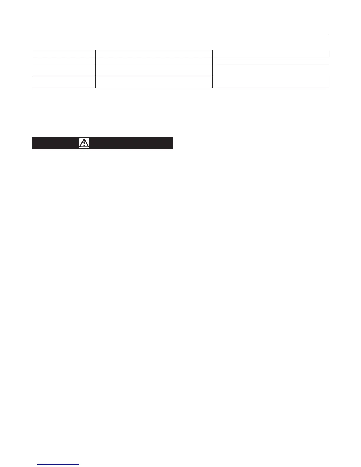
Table 2. Minimum and Maximum Limits for Setting Process Variables
Application Minimum Limit Maximum Limit
Liquid level Displacer must be completely out of liquid Displacer must be completely submerged in liquid
Interface
Displacer must be completely submerged in the upper
of two process liquids
Displacer must be completely submerged in the lower
of two process liquids
Density
Displacer must be completely submerged in liquid having
highest specific gravity expected
Displacer must be completely submerged in liquid
having the lowest specific gravity expected
SP GR
h
= Specific gravity of the heavier liquid at
operating temperature.
Calibration Procedure
WARNING
The following calibration procedure re-
quires taking the controller out of ser-
vice. To avoid personal injury and prop-
erty damage caused by an uncontrolled
process, provide some temporary
means of control for the process before
taking the controller out of service.
Figure 11 shows adjustment locations for the following
steps, except as otherwise indicated. When calibrat-
ing, open loop conditions must exist. One way to ob-
tain an open loop is to place the final control element
into manual control or bypass it. If there is no provision
for manual control, shut down the process. It is recom-
mended that a test pressure gauge be installed in the
controller output line for subsequent calibration steps.
Several steps in these calibration procedures require
setting the process variable at its minimum and maxi-
mum limits according to table 2. Reverse-acting con-
trollers produce the opposite response.
1. Connect a supply pressure source to the controller
and provide a supply pressure suitable for the sensing
element range: 20 psig (1.4 bar) for a 3 to 15 psig (0.2
to 1.0 bar) output pressure range or 35 psig (2.4 bar)
for a 6 to 30 psig (0.4 to 2.0 bar) output pressure range.
2. Rotate the reset knob to 0.01 minutes per repeat.
3. Rotate the proportional band knob to zero.
4. Set the liquid at the minimum limit (dry displacer).
5. Turn the raise level knob to zero.
6. Adjust the nozzle until output pressure is between
0 and 3 psig for a 3 to 15 psig signal range (0 and 0.2
bar for a 0.2 to 1.0 bar signal range) or 0 and 6 psig
for a 6 to 30 psig signal range (0 and 0.4 bar for a 0.4
to 2.0 bar signal range).
7. Set the liquid at the maximum limit (covered dis-
placer).
8. Turn the raise level knob until the output pressure is
15 psig for a 3 to 15 psig signal range (1.0 bar for a 0.2
to 1.0 bar signal range) or 30 psig for a 6 to 30 psig sig-
nal range (2.0 bar for a 0.4 to 2.0 bar signal range).
9. The controller is within its calibration accuracy if the
raise level knob is between the 9.0 and 10.0 positions.
10. If the controller is out of calibration, adjust the cal-
ibration adjuster as follows:
Note
Loosen the two calibration adjuster
screws (key 45, figure 16), and slide the
calibration adjuster (key 100, figure 16)
in the desired direction.
a. If output is below 15 psig for a 3 to 15 psig sig-
nal range (1.0 bar for a 0.2 to 1.0 bar signal range)
or 30 psig for a 6 to 30 psig signal range (2.0 bar
for a 0.4 to 2.0 bar signal range) , move the adjus-
tor a small distance away from the pivot to in-
crease span. Then repeat steps 4 through 9.
b. If output is above 15 psig for a 3 to 15 psig sig-
nal range (1.0 bar for a 0.2 to 1.0 bar signal range)
or 30 psig for a 6 to 30 psig signal range (2.0 bar
for a 0.4 to 2.0 bar signal range), move the adjustor
a small distance toward the pivot to decrease
span. Then repeat steps 4 through 9.
Note
If the controller cannot be calibrated,
look for other problems as described in
the Troubleshooting section, such as a
nonperpendicular flapper-nozzle condi-
tion, leaky connections, or a binding
displacer rod. If none of these troubles is
apparent, the displacer or torque tube is
probably sized for a different set of ser-
vice conditions. Ensure that the displacer
is sized correctly for the application.
Startup
Adjustment locations are shown in figure 11.
1. Set the raise level control to the desired control
point as determined in prestartup checks step 4.

 Loading...


