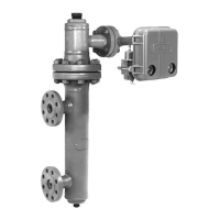
2502 Series
3
Table 1. Specifications
Available Configurations
Type 2502: A direct-acting controller which pro-
vides proportional-plus-reset control
Type 2502C: A Type 2502 with a level indicator
assembly
Type 2502F: A Type 2502 with a differential relief
valve
These type numbered products are also avail-
able with reverse action. For example, Type
2502R, Type 2502CR, and 2502FR
Input Signal
(1)
Liquid Level or Liquid-to-Liquid Interface Level:
From 0 to 100 percent of displacer length—stan-
dard lengths for all sensors are 14 inches (356 mm)
or 32 inches (813 mm). Other lengths available de-
pending on sensor construction
Liquid Density: From 0 to 100 percent of displace-
ment force change obtained with given displacer
volume—standard volumes are 60 inches
3
(980
cm
3
) for Types 249C and 249CP sensors, or 100
inches
3
(1640 cm
3
) for most other 249 Series sen-
sors; other volumes available depending on
construction
Output Signal
(1)
3 to 15 psig (0.2 to 1.0 bar) or 6 to 30 psig (0.4 to
2.0 bar)
Action: Field reversible between direct (increasing
liquid or interface leel or specific gravity increases
output pressure) and reverse (increasing liquid or
interface level or specific gravity decreases output
pressure)
Area Ratio of Relay Diaphragms
3:1
Supply Pressure Requirement
20
(2)
psig (1.4 bar) for 3 to 15 psig (0.2 to 1.0 bar)
output signal or 35
(2)
psig (2.4 bar) for 6 to 30 psig
(0.4 to 2.0 bar) output signal
Maximum Supply Pressure
50 psig (3.4 bar)
Supply Pressure Consumption
At 20 Psig (1.4 bar)
Minimum:
4.2 scfh
(3)
(0.11 m
3
/h) at proportional
band setting of 0 or 200 percent
Maximum:
27 scfh (0.72 m
3
/h) at proportional band
setting of 100 percent
At 35 psig (2.4 bar)
Minimum:
7 scfh (0.2 m
3
/h) at proportional band
setting of 0 or 200 percent
Maximum:
42 scfh (1.1 m
3
/h) at proportional band
setting of 100 percent
Performance
Hysteresis: 0.6 percent of output pressure change
at 100 percent of proportional band
Repeatability(1): 0.2 percent of displacer length or
displacement force change
Dead Band(1): 0.05 percent of proportional band or
span
Typical Frequency Response
(1)
: 4 Hz and 90-de-
gree phase shift at 100 percent of proportional band
with output piped to typical instrument bellows using
20 feet (6.1 meters) of 1/4 inch (6.4 mm) tubing
Ambient Temperature Error: 1.5 percent of out-
put pressure change per 50_F (28_C) of tempera-
ture change at 100 percent of proportional band
when using sensor with standard-wall N05500
(K-Monel
(4)
) torque tube with 249 Series sensors
Reset
(1)
: Adjustable from 0.01 to 74 minutes per
repeat (100 to 0.01 repeats per minute)
Differential Relief (Type 2502F and 2502FR Con-
trollers Only): Adjustable from 2 to 7 psi (0.1 to
0.48 bar differential) to relieve excessive difference
between proportional and reset pressures. Differen-
tial relief can be switched between rising output
pressure and falling output pressure.
Standard Tubing Connections
1/4 inch (6.4 mm) NPT female
Maximum Working Pressures (Sensors Only)
Consistent with aplicable ANSI pressure/tempera-
ture ratings
Operative Ambient Temperatures
Standard Construction: 40 to 160_F (40 to
71_C)
High Temperature Construction: 0 to 220_F
(18 to 104_C). See figure 2
1. Term defined in ISA Standard S51.1-1979.
2. Control and stability may be impaired if this pressure is exceeded.
3. Scfh=standard cubic feet per hour at 60_F and 14.7 psia (normal cubic meters per hour (m
3
/hr) at 0_C and 1.01325 bar).
4. K-Monel is a mark owned by Inco International.
 Loading...
