Type 4660
10
5. Repeat steps 1, 2, and 3 for the other module, if
specified.
Prestartup Checks
Before using the pilot in an actual startup, verify that
both the high and low set point pressures are set at
the desired pressure settings.
WARNING
To avoid personal injury or property
damage caused by a sudden release of
pressure, do not exceed the Bourdon
Tube rating (see tables 2 and 3).
1. After the desired low set point pressure has been
adjusted, increase the external pressure source pres-
sure until the output pressure of the pilot is at full out-
put. Do not exceed the set range (see tables 2 and 3)
for the appropriate Bourdon tube range.
2. Increase the external pressure source pressure until
the output pressure of the pilot has changed from full
output to zero. Listen carefully. You will hear a quick
change in sound when the output changes.
3. Compare the pressure of the external pressure
source with the desired high set point setting.
4. If necessary, adjust the high set point pressure by
turning the HIGH SET knob clockwise to increase and
counterclockwise to decrease the high set point set-
ting. Once the desired high set point is achieved, ro-
tate the locking arm to the locked position.
5. Decrease the external pressure source until the out-
put pressure of the pilot is again at full output.
6. Continue to decrease the external pressure source
pressure until the output pressure of the pilot has
changed from full output to zero. Listen carefully. You
will hear a quick change in sound when the output
changes.
7. Compare the pressure of the external pressure
source with the desired low set point setting.
8. If necessary adjust the low set point pressure by
turning the LOW SET knob (key 67) clockwise to in-
crease and counterclockwise to decrease the low set
point setting. Once the desired low set point is
achieved, rotate the locking arm to the locked position.
Alignment of the Nozzle Beam
Perform this procedure before startup if the self-align-
ing disk of the nozzle beam is noticeably misaligned
with respect to the nozzle area of the block-and-bleed
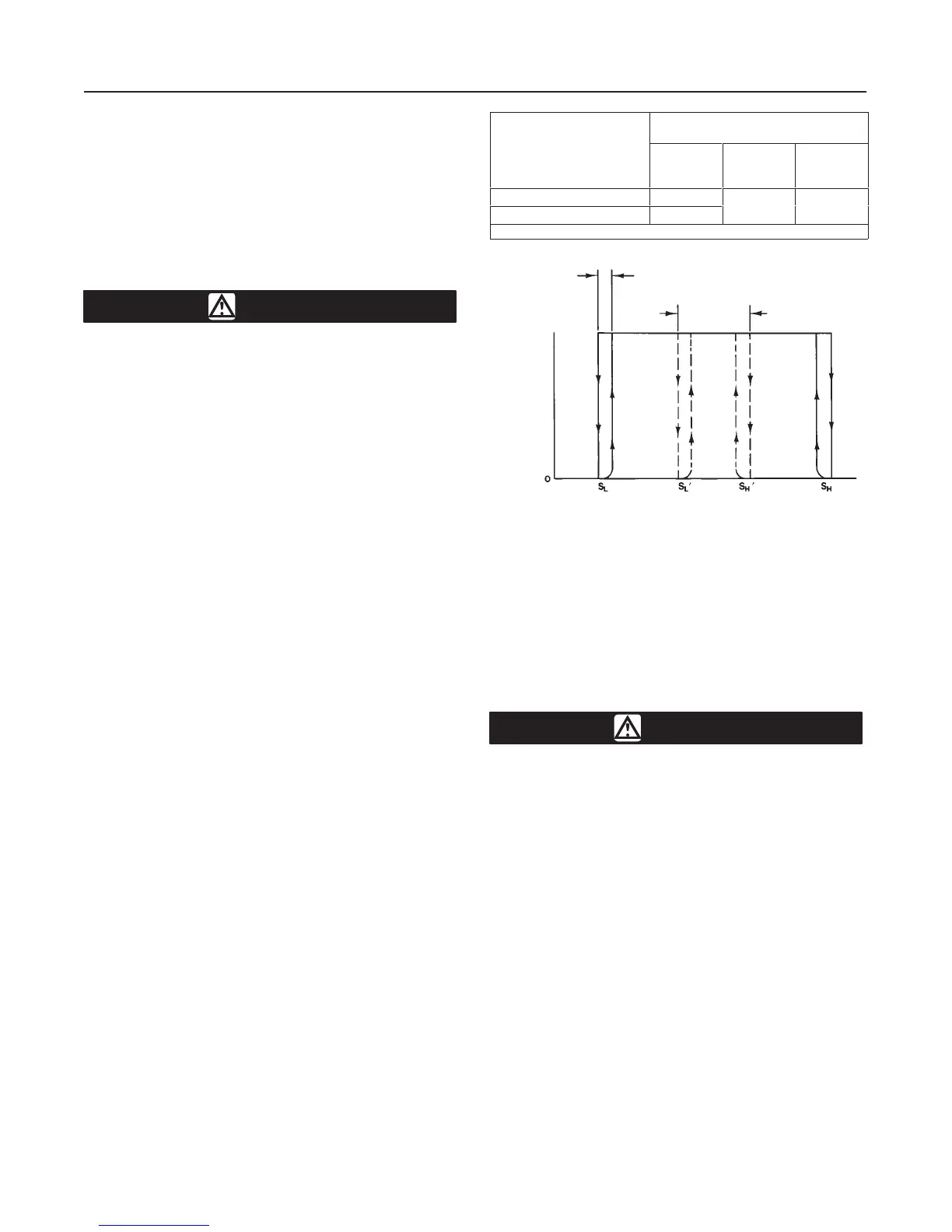
PERCENT OF BOURDON
TUBE RATING
CONSTRUCTION
Set Point
P
MIN
Trip-to-
Reset
Zone
Repeat-
ability
Single High-Low Unit 10
(1)
High-Only/Low-Only Pair 3
≤1.5 ≤0.25
1. 5000 and 7500 psig Bourdon tubes are 15 percent of Bourdon tube rating.
relay (see figures 7 and 8). Key numbers are shown in
figure 8.
1. Remove the case cover screw (key 5) and the case
cover (key 3).
2. Lift the end of the flapper off the nozzle beam
approximately 3/4-inch (19 mm) by moving the oppo-
site end of the flapper clockwise for a slight rotation.
CAUTION
Be careful not to force the flapper such
that the spring (key 18) will become
damaged.
3. Release the upper end of the flapper such that the
flapper will snap back and contact the nozzle beam.
4. Replace the case cover, and attach it with the case
cover screw.
Startup
Verify that the desired high and/or low set point pres-
sures have been set. Refer to the Mounting section for
the desired pilot installation procedures. Reduce the
external process pressure source to zero and discon-
nect the source from the process pressure connection.
Reconnect the process pressure line to the pilot and
open the process pressure line from the process to the
pilot. Reconnect the pilot output pressure line. When
adjustments and startup have been completed, re-
place the cover (key 4), and the cover screws (key 6).
Figure 6. Performance Characteristics
TRIP-TO-
RESET ZONE
SET POINT
∆P
MIN
100%
OUTPUT
PRESSURE
PROCESS PRESSURE
A2897-2
 Loading...