Type 4660
9
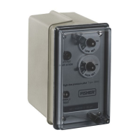
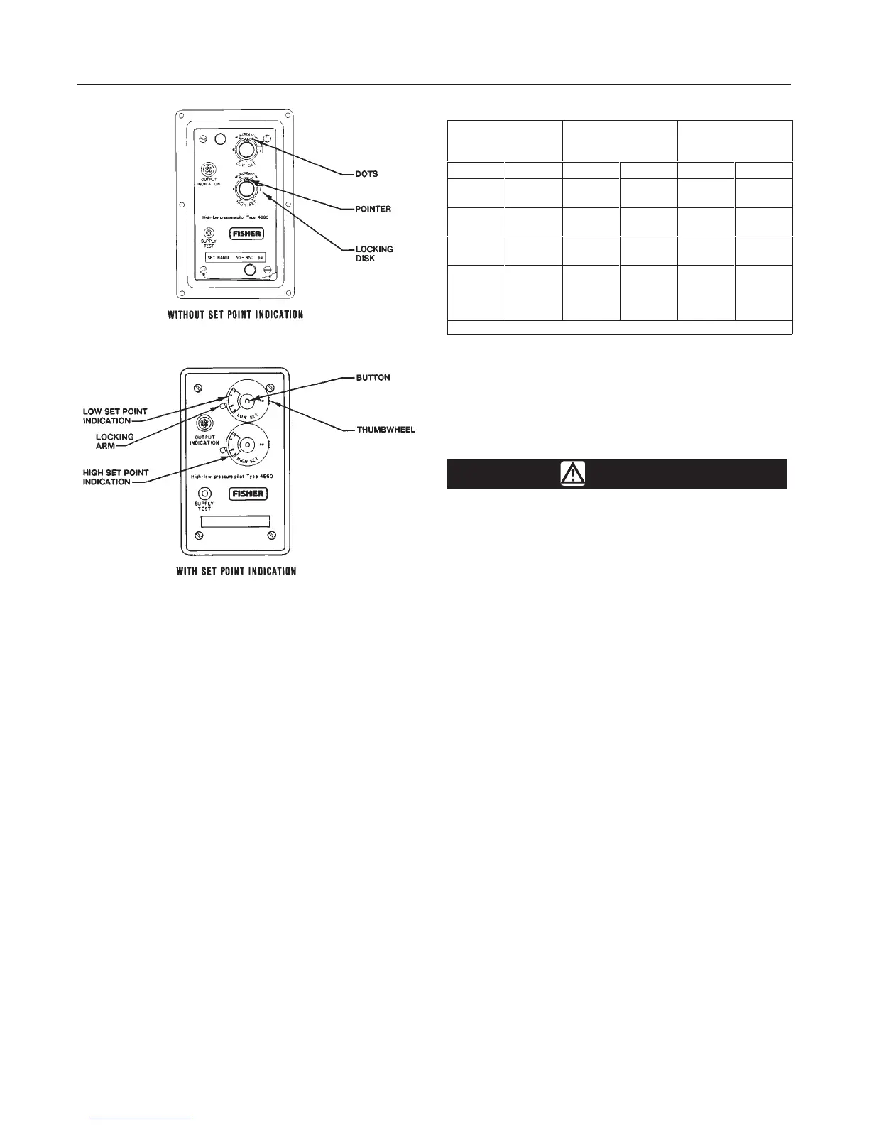
Figure 5. Set Point Adjustment Detail
48A3549-F
39A1578-A
A3300-1/IL
7. Turn the LOW SET knob clockwise until the low set
point pivot just comes in contact with the flapper, mov-
ing the nozzle beam off the nozzle. The pilot should
have zero output pressure (black indication on the op-
tional output indicator).
8. Refer to table 5 and turn the LOW SET knob clock-
wise to the desired set point value. For example, with
a 100 psig (690 kPa) Bourdon tube, turn the knob two
revolutions for a desired low set point of 24 psig (165
kPa).
9. Lock the locking disks (key 69).
Pilots With Optional Set Point Indication
Make sure each of the following five steps have been
performed completely before setting the high and/or
low set point pressures. Key numbers are shown in
figure 8.
1. Refer to the warning at the beginning of the Operat-
ing Information section. Be sure the Bourdon tube
contains no pressure.
2. Install either a pressure gauge or an optional output
indicator (key 88) in the output pressure line.
Table 5. Alternate Set Point Adjustment
BOURDON TUBE
RATING
PRESSURE
CHANGE
PER DOT
(1)
PRESSURE
CHANGE PER
REVOLUTION
Psig bar Psig bar Psig bar
50
100
3.4
6.9
1
2
0.1
0.1
6
12
0.4
0.8
250
500
17.2
34.5
5
10
0.4
0.7
30
60
2.1
4.1
1000
1500
69.0
103.4
20
30
1.4
2.1
120
180
8.3
12.4
2500
5000
7500
10,000
172.4
344.8
517.2
689.5
50
100
150
200
3.4
6.9
10.3
13.8
300
600
900
1200
20.7
41.4
62.1
82.7
1. Six dots per revolution.
3. Remove the cover screws (key 6) and the cover
(key 4).
4. Turn on the supply pressure. To check that the sup-
ply pressure is turned on, press the SUPPLY TEST
button located in the cleanout assembly (key 54) until
a flow sound is heard.
WARNING
To avoid personal injury or property
damage caused by a sudden release of
pressure, do not exceed the process
pressure values in table 4.
5. Connect an external pressure source to the process
pressure connection. This external pressure source
should be a regulated air or gas supply that is adjust-
able to zero. The external pressure source must be
capable of supplying a process pressure that will be
equal to or greater than the desired high set point
pressure.
6. Continue with the appropriate procedures described
below. Replace the cover and cover screws after all
adjustments are completed.
Setting the High and/or Low Set Point(s)
1. Adjust the external process pressure source to the
desired high or low set point. For example, if the pilot
is to trip at 50 psig (3.4 bar), apply 50 psig (3.4 bar) to
the pilot. Use a pressure gauge to measure the pro-
cess pressure.
2. Rotate the locking arm clockwise to unlock the mod-
ule. Slowly turn the HIGH SET or LOW SET knob until
the pilot trips.
3. Push the small button in the center of the knob with
a ball point pen or pencil and rotate the scale with the
thumbwheel on the right hand edge of the module (see
figure 5) until the number 50 aligns with the mark on
the left-hand edge of the module window.
4. Rotate the locking arm counterclockwise to lock the
module.