Type 667 Size 30-76 & 87
2
Table 1. Specifications
ACTUATOR SIZE
SPECIFICATION
30 34 40 45 46 50 60 70
(1)
76 87
(1)
Sq cm 297 445 445 667 1006 677 1006 1419 1006 1419
Nominal Effective Area
Sq Inch 46 69 69 105 156 105 156 220 156 220
mm 54 54 71 71 71 90 90 90 90 125
Yoke Boss Diameter
Inch 2-1/8 2-1/8 2-13/16 2-13/16 2-13/16 3-9/16 3-9/16 3-9/16 3-9/16 5
p
table Valve Stem Diameter
mm 9.5 9.5 12.7 12.7 12.7 19.1 19.1 19.1 19.1 25.4
Acceptable Valve Stem Diameter
Inch 3/8 3/8 1/2 1/2 1/2 3/4 3/4 3/4 3/4 1
p
N 10,230 10,230 12,010 25,131 33,582 25,131 30,246 39,142 30,246 39,142
Maximum Allowable Output Thrust
LB 2300 2300 2700 5650 7550 5650 6800 8800 6800 8800
mm 19 29 38 51 51 51 51 76
(3)
51 76
(3)
Standard
Inch 3/4 1-1/8 1-1/2 2 2 2 2 3
(3)
2 3
(3)
Maximum Travel
p
mm - - - 19 - - - 19 - - - - - - 29 - - - 29 76
Top-Loaded
Inch - - - 3/4 - - - 3/4 - - - - - - 1-1/8 - - - 1-1/8 3
Maximum Casing Pressure for
Bar 3.8 4.8 4.8 4.5 3.5 4.5 3.5 3.4 3.4 3.4
Actuator Sizing
(4,6)
Psig 55 70 70 65 55 65 55 50 50 50
Maximum Excess Diaphragm
Bar 3.9 1.4 1.4 0.7 0.7 0.7 0.7 0.7 0.7 0.7
Pressure
(4,5)
Psig 55 20 20 10 10 10 10 10 10 10
Maximum Diaphragm Casing
Bar 7.6 6.2 6.2 5.2 4.5 5.2 4.5 4.1 4.1 4.1
Pressure
(4,6,7)
Psig 110 90 90 75 65 75 65 60 60 60
pp
Kg 15 22 23 41 55 43 55 115 86 118
Approximate Weight
Pounds 34 48 50 90 121 94 122 254 190 260
Material
p
Nitrile Elastomers
–40 to 82_C (–40 to 180_F)
Temperature
Capabilities
Silicone Elastomers
–54 to 149_C (–65 to 300_F)
1. These values also apply to the Type 667-4 actuator construction.
2. Actuator travel may be less than the value listed after connected to the valve.
3. Maximum actuator travel for Type 667-4 is 102 mm (4 inches).
4. See also the Specification portion of the introduction section.
5. Additional pressure may be added when the actuator is at full travel. If the Maximum Excess Diaphragm Pressure is exceeded, damage to the diaphragm or diaphragm casing might
result. See the Maximum Pressure Limitation section.
6. Maximum diaphragm casing pressure must not be exceeded and must not produce a force on the actuator stem greater than the maximum allowable actuator output thrust or the
maximum allowable stem load. See the Maximum Pressure Limitation section.
7. This maximum casing pressure is not to be used for normal operating pressure. Its purpose is to allow for typical regulator supply settings and/or relief valve tolerances.
Introduction
Scope of Manual
This instruction manual provides information on instal-
lation, adjustment, maintenance, and parts ordering for
the Type 667 actuator in sizes 30 through 76 and size
87. The Type 667-4 actuator in sizes 70 and 87 is also
covered. Refer to separate instruction manuals for in-
formation about the valve positioner and other acces-
sories used with these actuators.
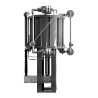
Only personnel qualified through training or experience
should install, operate, and maintain a Type 667 ac-
tuator (see figure 1). If you have any questions about
these instructions, contact your Fisher Controls sales
office or sales representative before proceeding.
Description
The Type 667 actuator (figure 1) and the Type 667-4
actuator are reverse-acting, spring-opposed dia-
phragm actuators. They provide automatic operation of
control valves. The Type 667 actuator provides 76 mm
(3 inches) maximum actuator travel. The Type 667-4
actuator provides 102 mm (4 inches) maximum actua-
tor travel. Both actuators position the valve plug in re-
sponse to varying pneumatic loading pressure on the
diaphragm. Figure 2 shows the operation of these ac-
tuators.
A Type 667 or 667-4 actuator can be furnished with
either a top-mounted or a side-mounted handwheel
assembly. A top-mounted handwheel assembly is nor-
mally used as an adjustable down travel stop. (A down
travel stop limits actuator travel in the down direction
[when the stem is traveling out of the actuator]. Travel
in the up direction is when the stem is traveling into the
actuator.) A side-mounted handwheel assembly is nor-
mally used as an auxiliary manual actuator. The side-
mounted handwheel can also be used as an adjust-
able up or down travel stop. Casing-Mounted
adjustable up or down travel stops are also available
on this actuator.