Type 667 Size 30-76 & 87
8
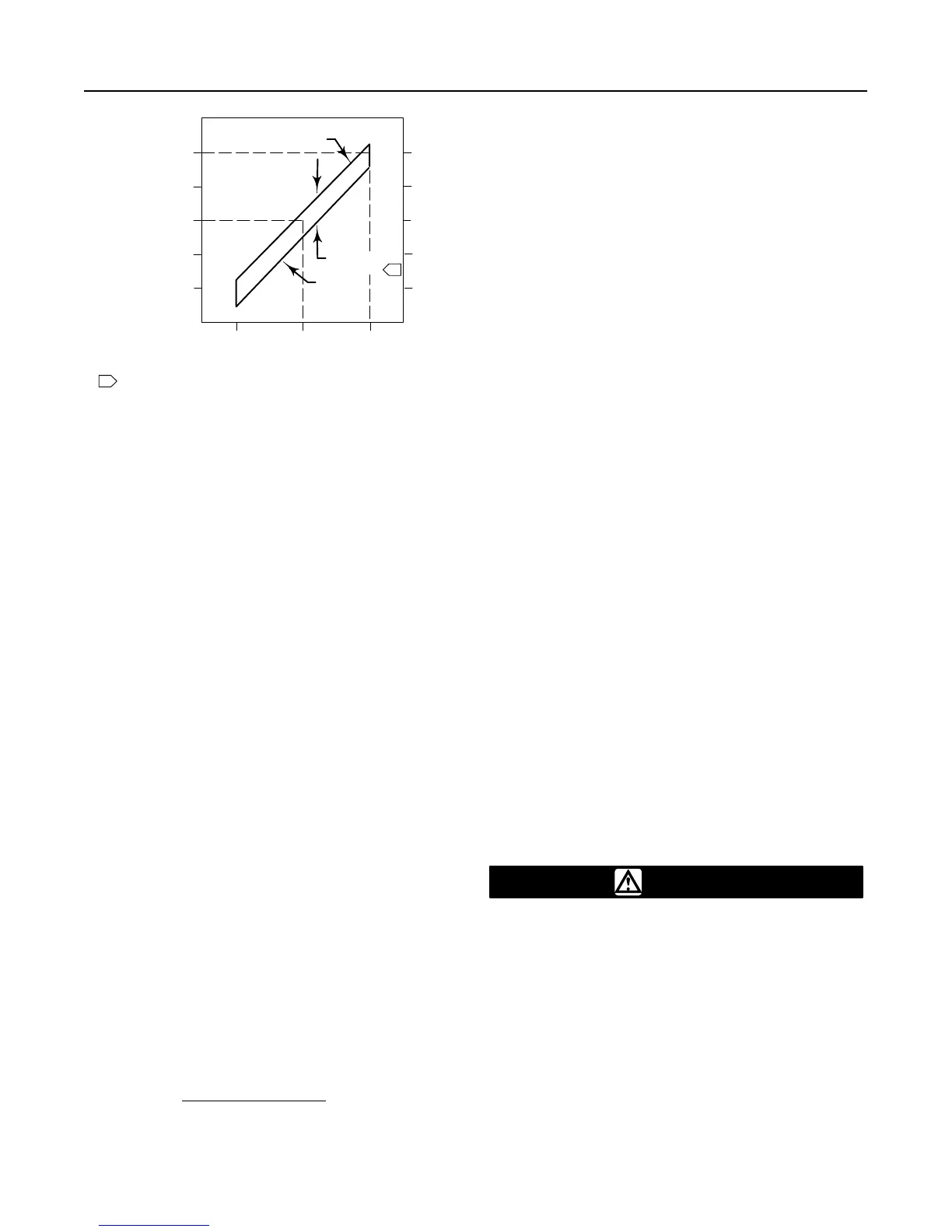
Figure 5. Typical Reverse-Acting Valve Response
to Deadband
UPPER
BENCH SET
PRESSURE
LOWER
BENCH SET
PRESSURE
9
3
0
OPENING
VALVE
15
1.0
0.6
0.2
CLOSING
VALVE
CLOSED
OPEN
MID RANGE
VALVE TRAVEL
DIAPHRAGM PRESSURE, PSIG
DIAPHRAGM PRESSURE, BAR
1
NOTE:
DEADBAND IS CAUSED BY FRICTION.
A6588-1 / IL
RANGE OF
DEADBAND
1
Deadband Measurement
Deadband is caused by packing friction, unbalanced
forces, and other factors in the control valve assembly.
Deadband is the range a measured signal can vary
without initiating a response from the actuator (see
figure 5). Each actuator spring has a fixed spring rate
(force). You have verified that the right spring was
installed in the actuator by completing the Bench Set
Spring Adjustment steps.
Deadband is one factor that affects the control valve
assembly operation during automatic loop control. The
control loop tolerance for deadband varies widely de-
pending on the loop response. Some common symp-
toms of the deadband being too wide are no move-
ment, a ‘‘jump” movement, or oscillating movements of
the actuator during automatic loop control. The follow-
ing steps are provided to determine the span of dead-
band. The percent of deadband is helpful in trouble-
shooting problems with the process control loop.
1. Start at a pressure near the lower bench set pres-
sure, slowly increase pressure until the valve is
approximately at mid-travel. Note this pressure read-
ing.
2. Slowly decrease pressure until movement of the
valve stem is detected, and note this pressure.
3. The difference between these two pressures is
deadband, in psi.
4. Calculate the percent of deadband by:
Deadband, psi
Deadband = Deadband, psi
= nn %
Bench Set Span, psi
Loading Connection
Key number locations are shown in figures 6, 7, and 8,
unless otherwise noted.
The loading pressure connections are made at the fac-
tory if the valve, actuator, and positioner come as a
unit. Keep the length of tubing or piping as short as
possible to avoid transmission lag in the control signal.
If a volume booster, valve positioner or other accesso-
ry is used, be sure that it is properly connected to the
actuator. Refer to the positioner instruction manual or
other manuals as necessary. For actuators shipped
separately or whenever the actuator pressure connec-
tions are installed, use the following steps:
1. Connect the loading pressure piping to the NPT
female connection in the side of the yoke (key 73).
2. For size 70 and 87 actuators, if necessary, remove
the 1/4-inch NPT bushing if a 1/2-inch NPT female
connection is needed to increase connection size. The
connection can be made with either piping or tubing.
3. Cycle the actuator several times to be sure that the
valve stem travel is correct when the correct pressure
ranges are applied to the diaphragm.
4. If valve stem travel appears to be incorrect, refer to
the Bench Set Spring Adjustment procedures at the
beginning of this section. Do not place the valve in ser-
vice if it is not reacting correctly to diaphragm loading
pressure changes.
Maintenance
Actuator parts are subject to normal wear and must be
inspected and replaced when necessary. The frequen-
cy of inspection and replacement depends on the se-
verity of service conditions. Because of the care Fisher
Controls takes in meeting all manufacturing require-
ments (heat treating, dimensional tolerances, etc.),
use only replacement parts manufactured or furnished
by Fisher Controls.
WARNING
Avoid personal injury or property dam-
age from sudden release of process
pressure or uncontrolled movement of
parts. Before performing any mainte-
nance operations:
D Always wear protective gloves,
clothing, and eyewear when performing
any maintenance operations to avoid
personal injury.
D Disconnect any operating lines pro-
viding air pressure, electric power, or a