Instruction Manual
D102013X012
8560 Valve
June 2017
3
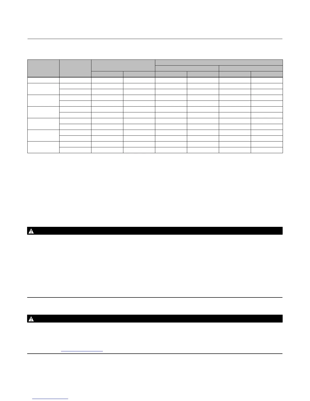
Table 2. Valve Size, Shaft Diameter, and Approximate Weight
VALVE SIZE,
NPS
CLASS
SHAFT DIAMETER
APPROXIMATE WEIGHT
Wafer‐Style Single‐Flange
mm Inches kg Pounds kg Pounds
2 150/300/600 12.7 1/2 4.3 9.5 ‐ ‐ ‐ ‐ ‐ ‐
3
150 12.7 1/2 4.5 10 6.4 14
300 15.9 5/8 5.9 13 11 25
4
150 15.9 5/8 8.6 19 11 24
300 19.1 3/4 10 23 18 39
6
150 19.1 3/4 13 29 16 35
300 25.4 1 15 33 27 59
8
150 25.4 1 21 47 27 59
300 31.8 1‐1/4 24 53 42 93
10
150 31.8 1‐1/4 34 75 40 88
300 38.1 1‐1/2 44 96 78 172
12
150 38.1 1‐1/2 49 107 62 137
300 44.5 1‐3/4 64 141 131 288
Installation
The valve is normally shipped as part of a control valve assembly, with the power actuator mounted on the valve. If the
valve or actuator have been purchased separately, or if the actuator has been removed for maintenance, mount the
actuator on the valve, and adjust actuator travel before inserting the valve body into the line. This is necessary due to
the measurements that must be made during the actuator calibration adjustment process. Refer to the Actuator
Mounting section of this manual to mount the actuator on the valve. Refer to the actuator instruction manual for
mounting and adjusting instructions before proceeding.
WARNING
Always wear protective gloves, clothing, and eyewear when performing any installation operations to avoid personal
injury.
To avoid personal injury or property damage resulting from the sudden release of pressure, do not install the valve
assembly where service conditions could exceed the limits given in this manual, the limits on the appropriate nameplates,
or the matching pipe flange rating. Use pressure‐relieving devices as required by government or accepted industry codes
and good engineering practices.
Check with your process or safety engineer for any additional measures that must be taken to protect against process
media.
If installing into an existing application, also refer to the WARNING at the beginning of the Maintenance section in this
instruction manual.
WARNING
The valve configuration and construction materials are selected to meet particular pressure, temperature, pressure drop,
and controlled fluid conditions. Responsibility for the safety of process media and compatibility of valve materials with
process media rests solely with the purchaser and end‐user. Since some valve body/trim material combinations are limited
in their pressure drop and temperature range capabilities, do not apply any other conditions to the valve without first
contacting your Emerson sales office
or Local Business Partner.