Instruction Manual
D104016X012
8590 Valve
June 2017
4
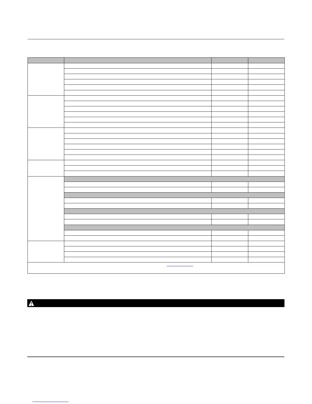
Table 4. Material Temperature Ranges
PART NAME MATERIAL TEMP _C TEMP _F
Valve Body
WCC Steel -29 to 427 -20 to 800
CF8M
(1)
-254 to 538 -425 to 1000
LCC -45 to 343 -50 to 650
CD3MN -51 to 316 -60 to 600
M35-2 -198 to 482 -325 to 900
CW2M
(1)
-198 to 538 -325 to 1000
Disk
CF8M with Chrome Plated Disk Edge -254 to 427 -425 to 800
CF8M with Chrome Coated Disk Edge
(1)
-254 to 538 -425 to 1000
CF8M with Chromium Carbide Disk Edge
(1)
-254 to 538 -425 to 1000
CD3MN (no plating)
(2)
-51 to 316 -60 to 600
M35-2 (no plating)
(2)
-198 to 482 -325 to 900
CW2M (no plating)
(1)(2)
-198 to 538 -325 to 1000
Shaft
S17400 (H1025) -46 to 427 -50 to 800
S20910
(1)
-198 to 538 -325 to 1000
S31803 -51 to 316 -60 to 600
N05500 -198 to 482 -325 to 900
N10276 -198 to 538 -325 to 1000
N07718
(1)
-254 to 538 -425 to 1000
Bearings
PEEK
(1)
-73 to 149 -100 to 300
S31600 Nitrided
(1)
-254 to 538 -425 to 1000
R30006 (Alloy 6)
(1)
-198 to 538 -325 to 1000
Seal
ETFE Soft Seal Ring
ETFE Soft Seal Ring with FKM Backup Ring -29 to 149 -20 to 300
ETFE Soft Seal Ring with EPR Backup Ring -54 to 149 -65 to 300
S20910/ETFE Phoenix III Seal Ring
S20910/ETFE Phoenix III Seal Ring with FKM Backup Ring -40 to 149 -40 to 300
S20910/ETFE Phoenix III Seal Ring with EPR Backup Ring -62 to 149 -80 to 300
Metal Seal
S21800
(1)
-198 to 538 -325 to 1000
S20910
(1)
-198 to 538 -325 to 1000
High Pressure Seal
S21800 Nitrided
(1)
-198 to 538 -325 to 1000
S20910 Nitrided
(1)
-198 to 538 -325 to 1000
Packing
PTFE /Carbon-filled PTFE (standard) -45 to 232 -50 to 450
ENVIRO-SEAL™ PTFE -45 to 232 -50 to 450
Graphite Die-molded Ribbon -198 to 538 -325 to 1000
ENVIRO-SEAL Graphite -198 to 371 -325 to 700
1. The maximum temperature for a standard design of the 8590 valve is 538_C (1000_F). Contact your Emerson sales office or Local Business Partner for use in higher temperature
applications.
2. For use with soft seal only.
Installation
Key numbers in this procedure are shown in figures 11, 12, and 13 unless otherwise indicated.
WARNING
Always wear protective gloves, clothing and eyewear when performing any installation operations to avoid personal
injury.
To avoid personal injury or property damage resulting from the bursting of pressure retaining parts, be certain the service
conditions do not exceed either the valve body rating or the flange joint rating, or other limits given in table 4 or on the
nameplate. Use pressure‐relieving or pressure‐limiting devices to prevent the service conditions from exceeding these
limits.
If installing into an existing application, also refer to the warning at the beginning of the Maintenance section on page 9 in
this manual.
 Loading...