Type 9500
3
age before placing the valve in service. If the valve
and actuator are being re-installed, after removal, or if
you suspect that the linkage is out of adjustment, refer
to the
Linkage
portion of the
Adjustments
section be-
fore installing the valve in the pipeline. If the valve has
been purchased separately, or if the actuator has been
removed, complete the procedures in the
Actuator
Mounting
section of this manual before proceeding.
WARNING
Avoid personal injury from sudden re-
lease of process pressure. Before per-
forming any maintenance operations:
D Disconnect any operating lines pro-
viding air pressure, electric power, or a
control signal to the actuator. Be sure
the actuator cannot suddenly open or
close the valve.
D Use bypass valves or completely
shut off the process to isolate the valve
from process pressure. Relieve process
pressure on both sides of the valve.
Drain the process media from both
sides of the valve.
D Vent the power actuator loading
pressure and relieve any actuator spring
precompression.
D Use lock-out procedures to be sure
that the above measures stay in effect
while you work on the equipment.
1. Isolate the control valve from the line pressure, re-
lease pressure from both sides of the valve body, and
drain the process media from both sides of the valve.
If continuous operation is required during inspection or
maintenance, install a three-valve bypass around the
control valve assembly.
2. Be certain the pipeline flanges are in line with each
other and supported.
3. Inspect the valve body to be sure it is free of for-
eign material. Make sure the adjacent piping is free of
pipe scale, welding slag, and any other material that
could damage valve seating surfaces.
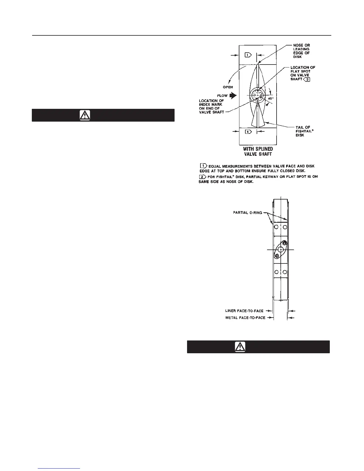
4. Measure to be sure the distance between the pipe-
line flanges is approximately 1/4 inch greater than the
valve face-to-face dimension. This will ensure easy
installation without distorting the liner (figure 3).
5. For conventional disks, flow may be in either direc-
tion; for Fishtail disks, flow must be such that the tail
of the disk (as shown in figure 2) will rotate into the
downstream side of the valve.
Figure 2. Valve Shaft Marking
A2755-1/IL
Figure 3. Partial O-Ring Location
A6017/IL
CAUTION
To avoid damaging valve parts, observe
the following precautions before insert-
ing the valve in the line.
a. The inside diameter of the mating piping or
flanges must be large enough to allow the valve
disk to rotate freely into the upstream and down-
stream piping, or the disk could be damaged.
b. The inside of the mating flange must also be
small enough to be in full contact with the partial