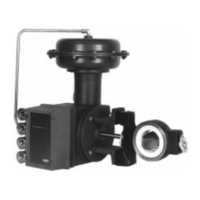
Type 9500
8
(0.38 mm) thick] of the mixture over all bonding
surfaces of the valve body and liner.
c. Insert the liner into valve body. Align the liner
shaft holes with valve body shaft holes. Remove
excess bonding agent from shaft holes and ex-
posed liner surfaces.
d. Insert disk (key 3), thrust sleeve assemblies
(key 6), and shaft (key 4) into the valve body. Be
sure thrust sleeve assemblies engage the liner re-
cesses to ensure proper liner positioning. Rotate
disk to closed position.
e. Lay the valve on one valve face and add
weights to the other face to ensure a tight bond.
Allow to cure for 24 hours. Then, proceed with the
following reassembly steps.
2. Insert thrust sleeve assemblies into valve body. Be
sure that the thrust sleeve assemblies enter the liner
recesses to align the shaft holes, by temporarily insert-
ing the shaft(s) (key 4).
3. A new disk and shaft should be installed if the taper
pin holes have been widened by loosening of taper
pins (key 15).
Omit the following steps 4 through 8 if a new disk and
shaft assembly is to be installed or if the old disk and
shaft are to be reused. Use new taper pins whenever
the disk has been removed.
CAUTION
If a new disk is required, a complete
disk/shaft assembly must be purchased
to avoid damage to valve parts.
If a new shaft (without disk) has been purchased, be
sure to mark the shaft to indicate disk position as
shown in figure 2.
4. Making certain the taper pin holes are on the ac-
tuator side of the valve body, insert the disk into the
valve body. Position the disk at the fully closed posi-
tion.
5. Installing splined shaft:
f. If the old shaft is available, insert it into the
valve body and disk. Line up the taper pin holes in
the disk and shaft; measure and record the dis-
tance between the valve body and the splined end
of the shaft. Remove the old shaft and insert the
new, un-drilled shaft. Position the shaft so that
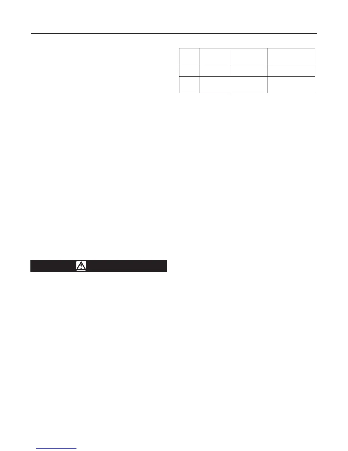
Table 4. Taper Pin Details for 9500 Series Valves
Valve
Size,
Inches
Shaft
Diameter,
Inches (mm)
American
Standard Taper
Pin Size
Drill Size
2
3, 4
1/2 (12.7)
5/8 (15.9)
2
3
#20 (0.161 Inches)
#16 (0.177 Inches)
6
8, 10
12
3/4 (19.1)
1 (25.4)
1-1/4 (31.8)
4
6
7
13/64 Inches
9/32 Inches
21/64 Inches
there is the same distance between the valve body
and end of the shaft as was noted above.
g. If installing a new shaft, insert the new shaft
into valve body and disk. Measure between the
valve body and the splined end of the shaft. Make
certain that distance is correct to engage the actua-
tor coupling lever.
Be certain that the flat spot or index mark on the end
of the shaft is positioned as shown in figure 2.
6. Use a drill or center punch to mark the taper pin
holes in the shaft. Remove shaft and disk from valve
body.
7. Taper pins used in Type 9500 valve shaft and disk
are American Standard taper pins as shown in table 4.
Using disk as a guide, drill taper pin holes through the
shaft using drill size shown in table 4.
8. Use an American Standard taper pin reamer to
ream the shaft holes. Be certain the reamer is of suffi-
cient length for the disk hub thickness. Insert the shaft
into the disk when reaming. In this way, the disk holes
can be used as a gauge for reaming. Allow the reamer
to just begin reaming the disk holes. This will ensure
proper seating of the pins.
9. Install disk and shaft into valve body. Be sure the
splined end of the shaft is on the actuator side of the
valve body, that the direction of taper in the taper pin
holes match, and that the flat spot or zero mark is
positioned as shown in figure 2.
10. Using a metal sealing compound on the pins for a
positive seal, insert taper pins into the larger end of the
taper pin holes. Drive pins with a hammer to seat pins.
11. Attach thrust plates (key 9) with cap screws (key
10). When tightening cap screws, do so in small incre-
ments, alternating from one cap screw to another and
from one valve side to the other. Tighten cap screws
until thrust plates contact the thrust sleeve assemblies
snugly. Then rotate the cap screws enough to move
the thrust plates 1/32 inch (0.8 mm) closer to the valve
body.
12. Re-attach the actuator according to the steps in
the
Actuator Mounting
section; then install the valve
according to the steps in the
Installation
section.
 Loading...