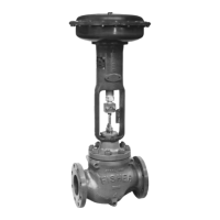
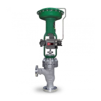
ES Valve
Instruction Manual
December 2008
6
WARNING
To avoid personal injury or property
damage caused by uncontrolled
movement of the bonnet, loosen the
bonnet by following the instructions in
the next step. Do not remove a stuck
bonnet by pulling on it with equipment
that can stretch or store energy in any
other manner. The sudden release of
stored energy can cause uncontrolled
movement of the bonnet. If the cage
sticks to the bonnet, proceed carefully
with bonnet removal.
Note
The following step also helps to
provide additional assurance that the
valve body fluid pressure has been
relieved.
3. Hex nuts (key 5, figure 8) attach the bonnet to the
valve. Loosen these nuts or cap screws
approximately 3 mm (1/8 inch). Then loosen the
body-to-bonnet gasketed joint by either rocking the
bonnet or prying between the bonnet and valve
body. Work the prying tool around the bonnet until
the bonnet loosens.
4. Loosen the packing flange nuts (key 5, figure 8)
so that the packing is not tight on the valve stem.
Remove any travel indicator parts from the valve
stem threads.
CAUTION
Avoid damage to the seating surface
caused by the valve plug and stem
assembly dropping from the bonnet
after being lifted part way out. When
lifting the bonnet, temporarily install a
valve stem locknut on the valve stem.
This locknut will prevent the valve
plug and stem assembly from
dropping out of the bonnet.
If the cage starts to lift with the
bonnet, tap it with a plastic mallet, or
other soft material, to be sure it stays
in the valve.
5. Completely remove the cap screws (not shown) or
hex nuts (key 16; figure 13, 14, or 15) that bolt the
bonnet and valve together and carefully lift the bonnet
off.
WARNING
To avoid personal injury due to leaking
fluid, avoid damaging gasket sealing
surfaces. The seating surface of the
valve plug (key 2) is critical for proper
shutoff. Protect these surfaces
accordingly.
6. Remove the locknut and separate the valve plug
and stem from the bonnet. Set the parts on a
protective surface to prevent damage to gasket or
seating surfaces.
CAUTION
To prevent possible product damage,
cover the opening in the valve in the
following procedure to prevent foreign
material from getting into the valve
body cavity.
7. Remove the bonnet gasket (key 10, figure 13
through 15) and cover the opening in the valve to
protect the gasket surface and prevent foreign
material from getting into the valve body cavity.
8. Remove the packing flange nuts, packing flange,
upper wiper, and packing follower (keys 5, 3, 12,
and 13, figure 8). Carefully push out all the
remaining packing parts from the valve side of the
bonnet using a rounded rod or other tool that will not
scratch the packing box wall. Clean the packing box
and the metal packing parts.
9. Inspect the valve stem threads and packing box
surfaces for any sharp edges which might cut the
packing. Scratches or burrs could cause packing box
leakage or damage to the new packing. If the
surface condition cannot be improved by light
sanding, replace the damaged parts by following the
appropriate steps in the Trim Maintenance
procedure.
10. Remove the covering protecting the valve body
cavity and install a new bonnet gasket (key 10,
figure 13 through 15), making sure the gasket
seating surfaces are clean and smooth. Then slide
the bonnet over the stem and onto the stud bolts
(key 15, figure 13, 14, or 15) or onto the valve body
cavity if cap screws (not shown) will be used instead.
Note
Proper performance of the bolting
procedures in step 11 compresses the
spiral wound gasket (key 12, figure 13