ES Valve
Instruction Manual
December 2008
5
Table 3. Body-to-Bonnet Bolt Torque Guidelines
VALVE SIZE, NPS BOLT TORQUES
(1)
ES EAS
SA193-B7, SA193-B8M
(3)
SA193-B8M
(2)
NSm LbfSft NSm LbfSft
1-1/4 or less 1 129 95 64 47
1-1/2, 1-1/2 x 1, 2, or 2 x 1 2 or 2 x 1 96 71 45 33
2-1/2 or 2-1/2 x 1-1/2 3 or 3 x 1-1/2 129 95 64 47
3, 3 x 2, or 3 x 2-1/2 4 or 4 x 2 169 125 88 65
4, 4 x 2-1/2, or 4 x 3 6 or 6 x 2-1/2 271 200 156 115
6 - - - 549 405 366 270
8 - - - 746 550 529 390
1. Determined from laboratory tests.
2. SA193-B8M annealed.
3. SA193-B8M strain hardened.
Packing Lubrication
Note
ENVIRO-SEAL or HIGH-SEAL packing
does not require lubrication.
WARNING
To avoid personal injury or property
damage resulting from fire or
explosion, do not lubricate packing
used in oxygen service or in
processes with temperatures over
260_C (500_F).
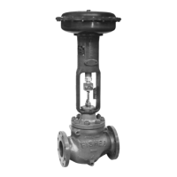
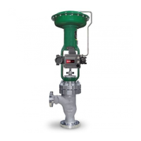
If a lubricator or lubricator/isolating valve (figure 2) is
provided for PTFE/composition or other packings
that require lubrication, it will be installed in place of
the pipe plug (key 14, figure 8). Use a good quality
silicon-base lubricant. Packing used in oxygen
service or in processes with temperatures over
260_C (500_F) should not be lubricated. To operate
the lubricator, simply turn the cap screw clockwise to
force the lubricant into the packing box. The
lubricator/isolating valve operates the same way
except the isolating valve must first be opened and
then closed after lubrication is completed.
Packing Maintenance
Key numbers refer to figure 3 for PTFE V-ring
packing and to figure 5 for PTFE/composition
packing, unless otherwise indicated.
For spring-loaded single PTFE V-ring packing, the
spring (key 8, figure 3) maintains a sealing force on
the packing. If leakage is noted around the packing
follower (key 13, figure 3), check to be sure the
shoulder on the packing follower is touching the
bonnet. If the shoulder is not touching the bonnet,
tighten the packing flange nuts (key 5, figure 8) until
the shoulder is against the bonnet. If leakage cannot
be stopped in this manner, proceed to the replacing
packing procedure.
If there is undesirable packing leakage with other
than spring-loaded packing, first try to limit the
leakage and establish a stem seal by tightening the
packing flange nuts.
If the packing is relatively new and tight on the stem,
and if tightening the packing flange nuts does not
stop the leakage, it is possible that the valve stem is
worn or nicked so that a seal cannot be made. The
surface finish of a new valve stem is critical for
making a good packing seal. If the leakage comes
from the outside diameter of the packing, it is
possible that the leakage is caused by nicks or
scratches around the packing box wall. If performing
any of the following procedures, inspect the valve
stem and packing box wall for nicks and scratches.
Replacing Packing
WARNING
Refer to the WARNING at the
beginning of the Maintenance section
in this instruction manual.
1. Isolate the control valve from the line pressure,
and release pressure from the valve.
2. Disconnect the operating lines from the actuator
and any leak-off piping from the bonnet. Disconnect
the stem connector, then remove the actuator from
the valve by unscrewing the yoke locknut (key 15,
figure 8) or the hex nuts (key 26, figure 8).