ES Valve
Instruction Manual
December 2008
8
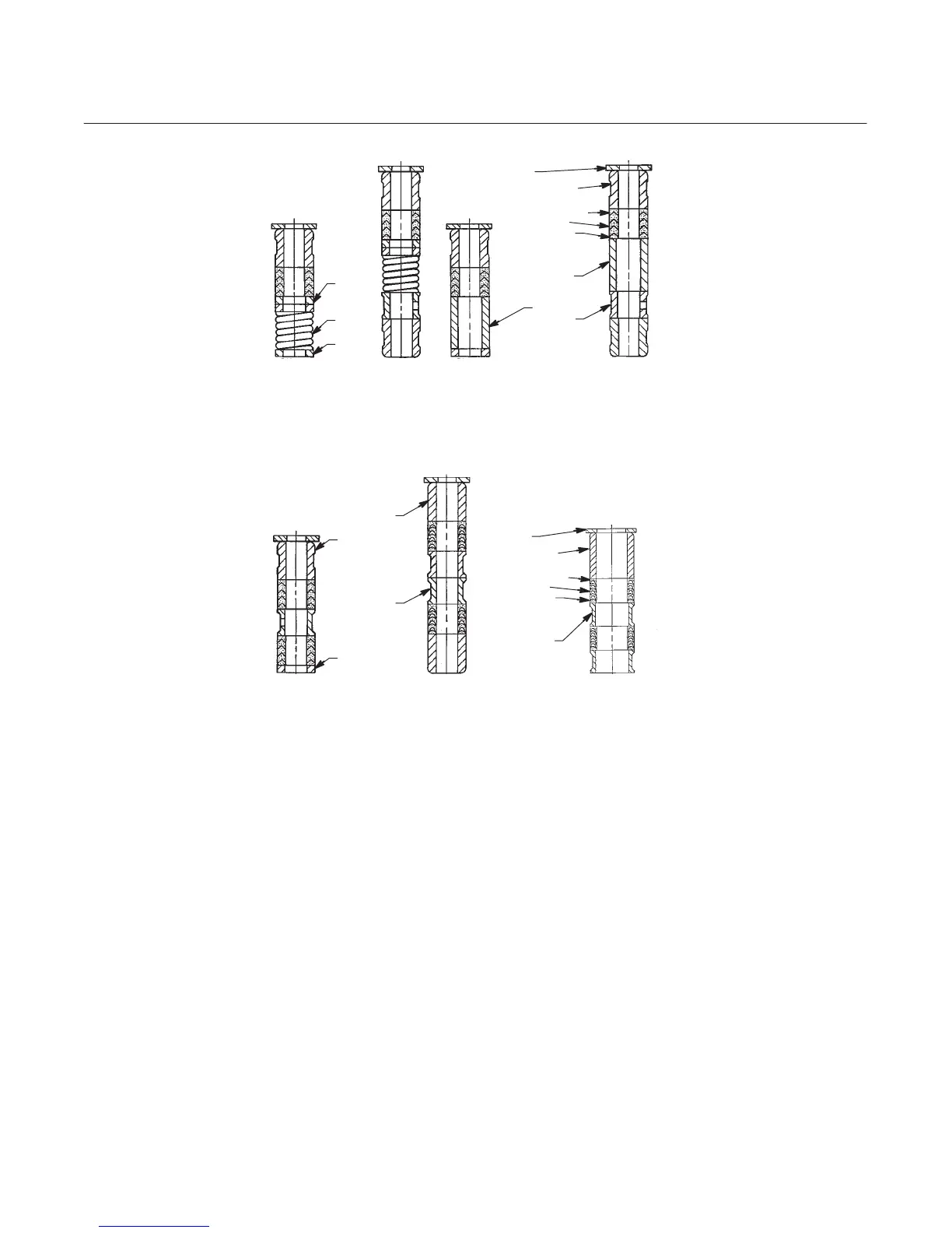
Figure 4. PTFE Packing Arrangements for Use in ENVIRO-SEALr Bellows Seal Bonnets
UPPER WIPER
(KEY 12)
PACKING SET: (KEY 6)
FEMALE ADAPTOR
PACKING RING
MALE ADAPTOR
BUSHING (KEY 13)
9.5 mm
(3/8 INCH)
STEM
12.7 mm
(1/2 INCH)
STEM
DOUBLE ARRANGEMENTS
9.5 mm
(3/8 INCH)
STEM
9.5 mm
(3/8 INCH)
STEM
12.7 mm
(1/2 INCH)
STEM FOR
NPS 2 VALVES
12.7 mm
(1/2 INCH)
STEM FOR
NPS 3 AND 4
VALVES
THRUST
RING
(KEY 39)
SPRING
(KEY 8)
THRUST
RING
(KEY 39)
THRUST
RING
(KEY 39)
BUSHING
(KEY 13)
BUSHING
(KEY 13)
SPACER
(KEY 8)
SPACER
(KEY 8)
SPACER
(KEY 8)
12.7 mm
(1/2 INCH)
STEM
SINGLE ARRANGEMENTS
FOR S31600 (316 SST)
PACKING BOX PARTS
FOR ALL PACKING BOX
MATERIALS EXCEPT S31600
UPPER WIPER
(KEY 12)
PACKING SET: (KEY 6)
FEMALE ADAPTOR
PACKING RING
MALE ADAPTOR
BUSHING (KEY 13)
SPACER
(KEY 8)
A5863-1 / IL
12B4183-A 18A0906-D 18A5338-A
12B4182-A SHT 1
12B4185-A SHT 1
12B4182-A SHT 2
12B4185-A SHT 2
11. Install bolting, using proper bolting procedures
during tightening so that the body-to-bonnet joint will
withstand test pressures and application service
conditions. The bolt torques in table 3 may be used
as guidelines.
12. Install new packing and the metal packing box
parts according to the appropriate arrangement in
figure 3, 5, or 6. For split ring packing, alternate the
positions of the splits to avoid creating a leak path.
Place a smooth-edged pipe over the valve stem and
gently tap each soft packing part into the packing
box, being sure that air is not trapped between
adjacent soft parts.
13. Slide the packing follower, upper wiper, and
packing flange (keys 13, 12, and 3, figure 8) into
position. Lubricate the packing flange studs (key 4,
figure 8) and the faces of the packing flange nuts
(key 5, figure 8). Install the packing flange nuts.
14. For spring-loaded PTFE V-ring packing,
tighten the packing flange nuts until the shoulder on
the packing follower (key 13, figure 8) contacts the
bonnet.
For ENVIRO-SEAL or HIGH-SEAL live-loaded
packing, refer to the note at the beginning of the
Maintenance section.
For graphite packing, tighten the packing flange nuts
to the maximum recommended torque shown in
table 4. Then, loosen the packing flange nuts, and
retighten them to the recommended minimum torque
shown in table 4.
For other packing types, tighten the packing flange
nuts alternately in small equal increments until one