Instruction Manual Supplement
D103783X012
DVC2000 Digital Valve Controller
September 2017
18
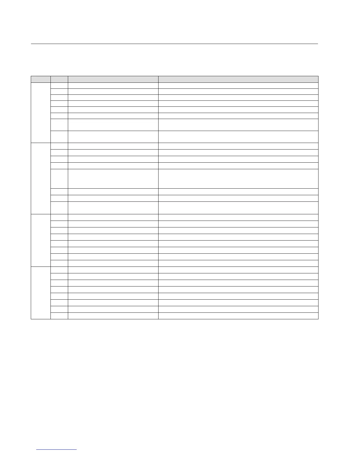
Additional Device Status
Byte Bit Name of Status Bit Meaning
3
7 Reserved
6 Reserved
5 Reserved
4 Reserved
3 Reserved
2 Reserved
1
Integrator Saturated High
Alert
Active if the instrument integrator is saturated at the high
extreme.
0
Integrator Saturated Low
Alert
2
Active if the instrument integrator is saturated at the low extreme.
4
7 Travel Alert Lo
2
Active when the Travel is below the Travel Alert Lo Point.
6 Travel Alert Lo Lo
2
Active when the Travel is below the Travel Alert Lo Lo Point.
5 Travel Alert Hi
2
Active when the Travel exceeds the Travel Alert Hi Point.
4 Travel Alert Hi Hi
2
Active when the Travel exceeds the Travel Alert Hi Hi Point.
3 Travel Deviation Alert
2
Active if the difference between the Travel Target and the Travel
exceeds the Travel Deviation Alert Point for more than the Travel
Deviation Time.
2 Travel Limit/Cutoff Hi Alert Active when the Travel exceeds the Hi Limit/Cutoff Point.
1 Travel Limit/Cutoff Lo Alert Active when the Travel falls below the Lo Limit/Cutoff Point.
0 Drive Signal Alert
2
Active when the Drive Signal exceeds target limits (<10% or
>90%) for more than 20 seconds when not in Cutoff condition.
5
7 Reserved
6 Reserved
5 Reserved
4 Reserved
3 Reserved
2 Option Module Error
1 Limit Switch 2 Status Set to “1” if Limit Switch 2 is enabled, powered, and closed.
0 Limit Switch 1 Status Set to “1” if Limit Switch 1 is enabled, powered, and closed.
6
7 Reserved
6 Reserved
5 Reserved
4 Reserved
3 Reserved
2 Reserved
1 Reserved
0 Reserved
"Reserved" bits are always set to 0.
1. Sets “Field Device Malfunction”.
2. Sets “More Status Available”.
 Loading...


