Instruction Manual Supplement
D103783X012
DVC2000 Digital Valve Controller
September 2017
6
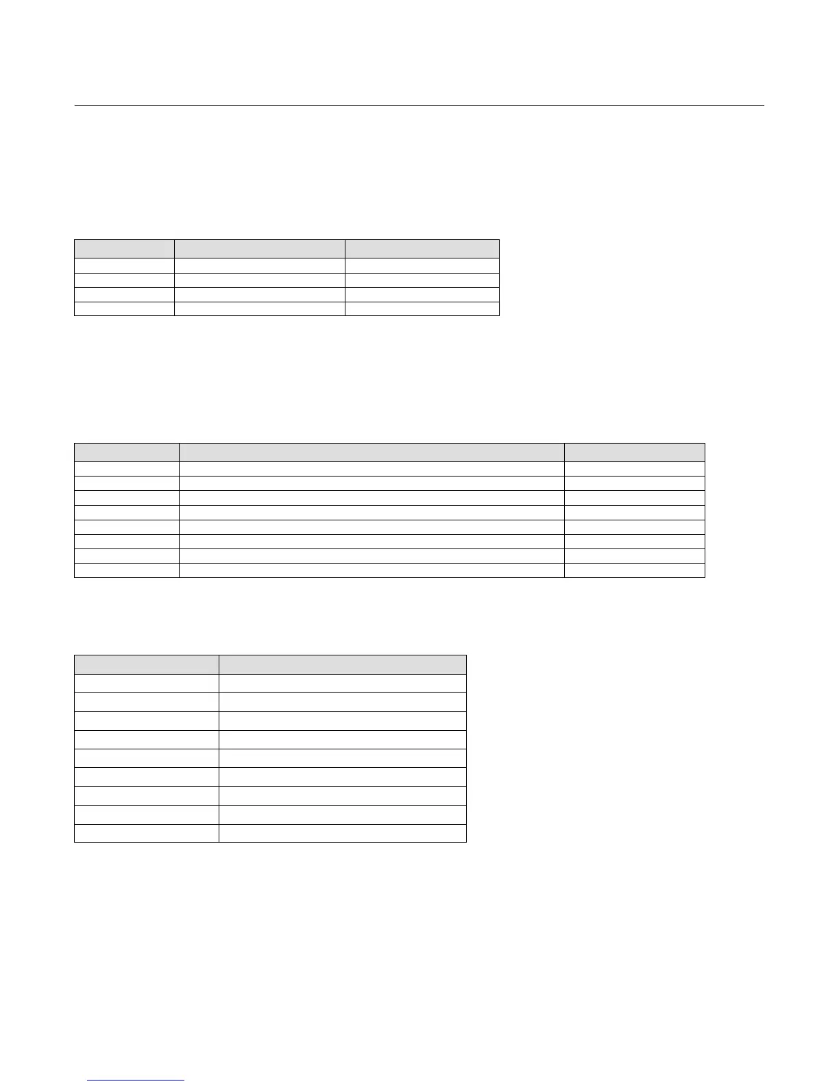
Dynamic Variables
Four Dynamic Variables are implemented.
Default Meaning Units
PV Analog Input mA, %
SV Travel Setpoint %
TV Pressure PSI, BAR, KPA
FV Travel %
Device Variables
These variables represent measurements taken by the device, are read only values, and are all in float format. These
can be read with Commands 33 and 54.
Variable ID Meaning Units
0 Analog Input mA, %
2 Pressure Port A PSI, BAR, KPA
3 Travel %
4 Drive Signal %
6 Travel Setpoint %
9 Implied Valve Position (Travel Target) %
10 Primary Feedback (user selected, either Travel or Pressure) %
211 Temperature _C or _F
Unit Codes
Variable Units Code Units
0 No Units
6 Pounds per square inch, psi
7 Bar
10 ($0A) Kilograms per square centimeter, kg/cm
2
12 ($0C) Kilopascals, kPa
32 ($20) Celsius, _C
33 ($21) Fahrenheit, _F
39 ($27) Milliamps, mA
57 ($39) Percent, %
 Loading...


