Instruction Manual Supplement
D103783X012
DVC2000 Digital Valve Controller
September 2017
25
Device Status:
The eight standard status conditions (present in ANY HART field device) are all represented by a Boolean “true” or
“false” state. These eight conditions, discussed on page 7, are:
D DEVICE_MALFUNCTION
D CONFIGURATION_CHANGED
D COLD_START
D MORE_STATUS_AVAILABLE
D LOOP_CURRENT_FIXED
D LOOP_CURRENT_SATURATED
D NONPRIMARY_VALUE_OUT_OF_LIMITS
D PRIMARY_VALUE_OUT_OF_LIMITS
Detailed Device Alerts:
The Alert Groupings are:
D ADDITIONAL_STATUS_0
D ADDITIONAL_STATUS_1
D ADDITIONAL_STATUS_2
D ADDITIONAL_STATUS_3
D ADDITIONAL_STATUS_4
D ADDITIONAL_STATUS_5
D ADDITIONAL_STATUS_6
D ADDITIONAL_STATUS_7
Each of these status bytes represent eight individual bits with values that range from “00” to “255”. To determine
which of the eight bits are active requires converting a decimal value to its binary equivalent value. Refer to Command
48 on page 17 for details on the individual alert bits inside of each Additional Status Byte.
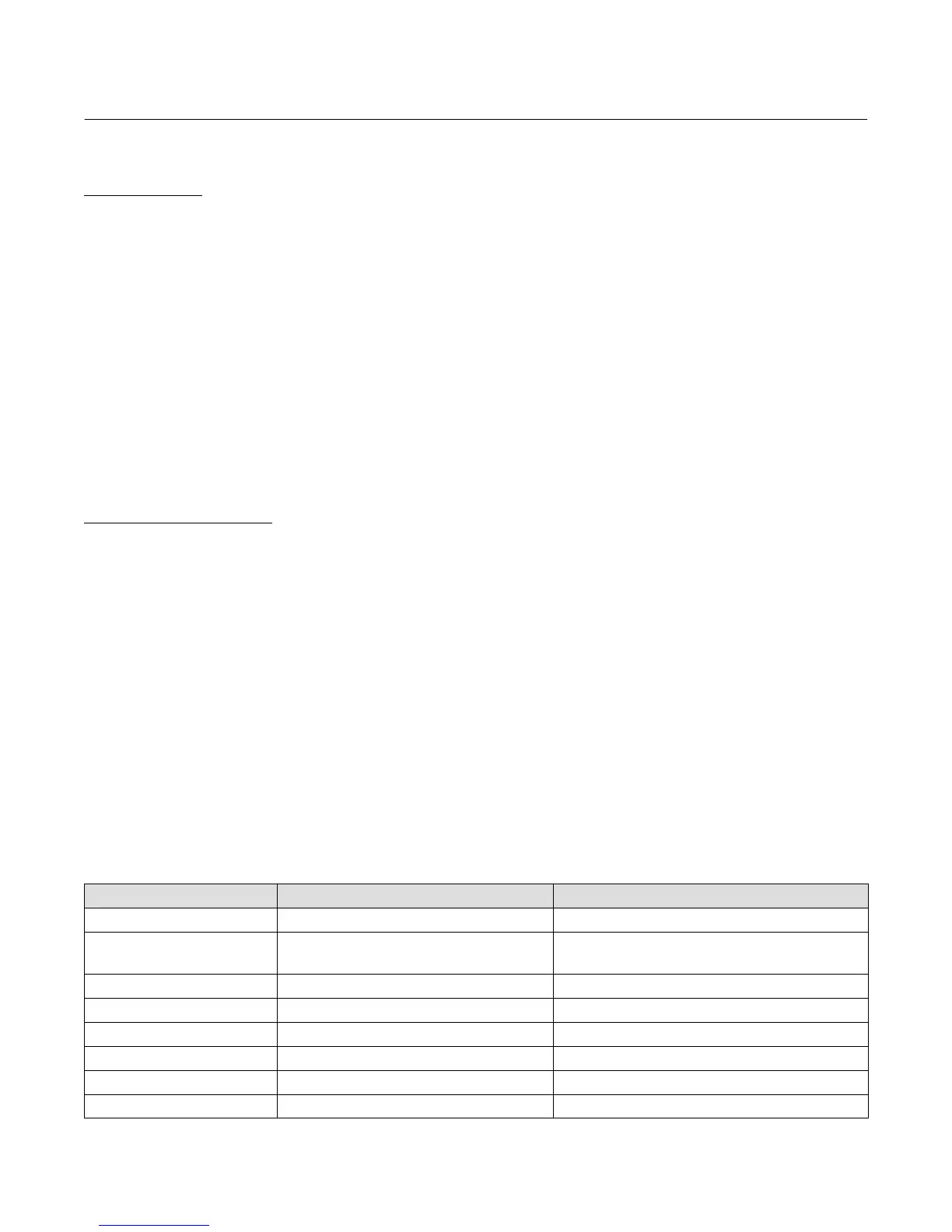
ADDITIONAL_STATUS_0 According to Command 48: As defined in the Gateway:
Bit 7 Flash Integrity Failure FLASH_ROM_FAIL
Bit 6
Temperature Compensation Data
Integrity Error
TEMPERATURE_COMPENSATION_FAIL
Bit 5 Reference Voltage Failure REFERENCE_VOLTAGE_FAIL
Bit 4 Drive Current Failure DRIVE_CURRENT_FAIL
Bit 3 Critical NVM Failure NVM_FAIL
Bit 2 Temperature Sensor Failure TEMPERATURE_SENSOR_FAIL
Bit 1 Pressure Sensor Failure PRESSURE_SENSOR_FAIL
Bit 0 Travel Sensor Failure TRAVEL_SENSOR_FAIL
 Loading...


