Instruction Manual
D103175X012
GX Valve and Actuator
July 2017
28
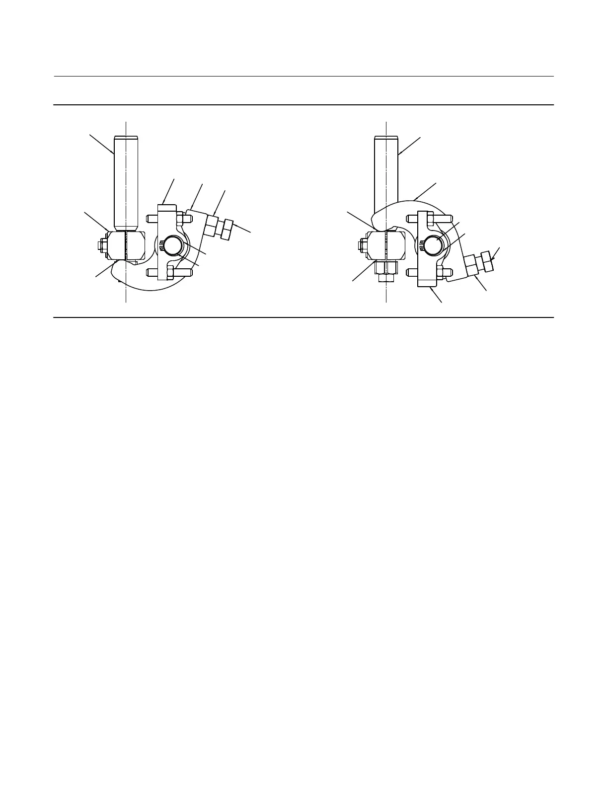
Figure 9. Fisher GX Travel Stop Orientation
ACTUATOR
ROD
ACTUATOR
ROD
STEM
CONNECTOR
STEM
CONNECTOR
APPLY
LITHIUM
GREASE TO
LEVERS
APPLY
LITHIUM
GREASE TO
LEVERS
BRACKET
BRACKET
BACK NUT (2)
BACK NUT (2)
LEVER
LEVER
SHAFT
SHAFT
RETAINING RING
RETAINING RING
ADJUSTABLE
CAP SCREW (2)
ADJUSTABLE
CAP SCREW (2)
DOWNSTOP
UPSTOP
Setting the Travel Stop Position
After sending the required position air signal to the actuator, screw the adjustable cap screws to assure the lever
contacts with the stem connector tightly, then tighten the back nut. Check the actual stem position when giving the
100% air signal.
Standard Accuracy for the travel stop position is +/- 10% for 20 mm travel. For added precision, use the following
procedure.
1. Send the desired position air signal to the actuator.
2. Set the travel stop, screw the adjustable cap screws to assure the lever contacts with the stem connector tightly,
then tighten the back nut.
3. Send a 100% air signal.
4. Measure the difference between the actual stem position and the desired position.
5. Send the air signal for the desired position minus the differential position measured in step 4.
6. Reset the travel stop by adjusting the two cap screws and then tighten the back nut.
 Loading...


