MR95 Series
4
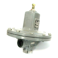
Figure 2. MR95 Series Operational Schematics
INLET PRESSURE
OUTLET PRESSURE
ATMOSPHERIC PRESSURE
SPRING
GASKET
METAL DIAPHRAGMS
TYPE MR95H WITH 2 METAL DIAPHRAGMS (ALSO TYPICAL OF
TYPES MR95HT AND MR95L EXCEPT FOR TYPE MR95L WITH 1/4 NPT
BODY SIZE, 2 to 6 psi / 0.14 to 0.41 bar RANGE)
SPRING
GASKET
METAL DIAPHRAGM
TYPE MR95L (1/4 NPT, 2 to 6 psi / 0.14 to 0.41 bar RANGE)
WITH METAL DIAPHRAGM
CONTROL LINE TAP
FRONT AND INTERNAL VIEW OF
TYPE MR95H WITH INTERNAL
PRESSURE REGISTRATION
BACK VIEW OF
1/2 IN. / DN 15 TYPE MR95H
WITH EXTERNAL
PRESSURE REGISTRATION
SIDE AND INTERNAL VIEW OF
3/4 TO 2 IN. / DN 20 TO 50
TYPE MR95H WITH EXTERNAL
PRESSURE REGISTRATION
(ALSO TYPICAL OF TYPE MR95L,
1/2 TO 2 IN. / DN 15 TO 50 BODY SIZES)
Principle of Operation
For Types MR95H, MR95L,
MR95HP and MR95HT
Pressure Reducing Regulators
Types MR95L, MR95H, MR95HP and MR95HT
(see Figure 2) are direct-operated regulators
and use spring force to regulate outlet pressure.
Downstream pressure is registered either internally
through the body or externally through a control
line to the under side of the diaphragm. When the
downstream pressure is at or above the set pressure,
the disk is held against the orice and restricting
ow through the regulator. When demand increases,
downstream pressure drops slightly allowing the spring
to extend, moving the stem down and the disk away
from the orice. This allows uid ow through the body
to the downstream system.
ADJUSTING SCREW
CONTROL SPRING
DIAPHRAGM
PITOT TUBE
VALVE PLUG
STEM
 Loading...


