EasyManua.ls Logo

Fisher V150 User Manual

Fisher V150
20 pages
To Next Page IconTo Next Page
Page #1 background imageLoading...
Page #1 background image
D101957X012
1. Design V150 is available in 14, 16, and 20-inch sizes. Design V300 is avail-
able in 14 and 16-inch sizes.
  


  

Introduction
1. . . . . . . . . . . . . . . . . . . . . . . . . . . . . . .
Scope of Manual 1. . . . . . . . . . . . . . . . . . . . . . . . . . . . .
Description 1. . . . . . . . . . . . . . . . . . . . . . . . . . . . . . . . . .
Specifications 2. . . . . . . . . . . . . . . . . . . . . . . . . . . . . . .
Installation
3. . . . . . . . . . . . . . . . . . . . . . . . . . . . . . . .
Maintenance
4. . . . . . . . . . . . . . . . . . . . . . . . . . . . . .
Packing Maintenance 5. . . . . . . . . . . . . . . . . . . . . . . . .
Stopping Leakage 5. . . . . . . . . . . . . . . . . . . . . . . . . .
Packing Replacement 5. . . . . . . . . . . . . . . . . . . . . . .
Disassembly 5. . . . . . . . . . . . . . . . . . . . . . . . . . . . . .
Assembly 6. . . . . . . . . . . . . . . . . . . . . . . . . . . . . . . . .
Ball Seal Replacement 6. . . . . . . . . . . . . . . . . . . . . . . .
Disassembly 8. . . . . . . . . . . . . . . . . . . . . . . . . . . . . . .
Assembly 9. . . . . . . . . . . . . . . . . . . . . . . . . . . . . . . . . .
Bearing and V-Notch Ball Maintenance 9. . . . . . . . . .
Disassembly 10. . . . . . . . . . . . . . . . . . . . . . . . . . . . .
Assembly 10. . . . . . . . . . . . . . . . . . . . . . . . . . . . . . . .
Actuator Mounting 12. . . . . . . . . . . . . . . . . . . . . . . . .
Determining Open Position 14. . . . . . . . . . . . . . . . .
Parts Ordering
14. . . . . . . . . . . . . . . . . . . . . . . . . . .
Parts List
15. . . . . . . . . . . . . . . . . . . . . . . . . . . . . . . . .

Scope of Manual
This instruction manual provides installation, opera-
tion, maintenance, and parts ordering information for
14, 16, and 20-inch Design V150 and for 14 and
16-inch Design V300 rotary control valves. For small
valves (2 through 12-inch size), refer to a separate
instruction manual. For information on
ENVIRO-SEALt packing, see the Fisher Controls
instruction manual titled
ENVIRO-SEAL Packing
System for V-Line and
ediscR
Rotary Valves
. Refer to
separate manuals for information concerning the ac-
tuator, positioner, and mounted accessories.
Figure 1. Design V150 and V300 Vee-Ball
R
Size 16-Inch Valve
W6087/IL
Only personnel qualified through training or experience
should install, operate, and maintain a Design V150 or
V300 valve. If you have any questions about these
instructions, contact your Fisher Controls sales office
or sales representative before proceeding.
Description
The Design V150 or V300 Vee-BallR valve with a
V-notch ball is used in throttling or on-off service. The
Design V150 valve (figure 1) is a raised-face flanged
construction available in ANSI Class 150. The Design
V300 valve is a raised-face flanged construction avail-
able in ANSI Class 300. The splined valve shaft con-
nects to a variety of rotary actuators.
Instruction Manual
Form 5316
March 199514 through 20-Inch Design V150 and V300
Question and Answer IconNeed help?

Do you have a question about the Fisher V150 and is the answer not in the manual?

Fisher V150 Specifications

General IconGeneral
Shutoff ClassificationClass IV
ActuationPneumatic
MaterialsCarbon Steel, Stainless Steel
Operating Temperature-50°F to 450°F (-46°C to 232°C)
ApplicationGeneral Purpose
Input VoltageNot applicable (valve only)
Communication ProtocolNot applicable (valve only)
Enclosure RatingNot applicable (valve only)
MountingFlanged
Output CurrentNot applicable (valve only)

Summary

Introduction

Scope of Manual

Defines the scope of the instruction manual for V150 and V300 valves.

Description

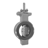
Describes the Design V150 and V300 Vee-Ball® valve features and applications.

Installation

Valve and Pipeline Preparation

Steps for preparing the valve and pipeline before installation, including flange alignment and gasket use.

Actuator Mounting

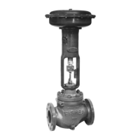
Instructions for mounting the actuator onto the valve, including pre-shipment adjustments.

Hazardous Area Bonding

Guidance on installing an optional bonding strap for safety in hazardous environments.

Maintenance

General Maintenance Precautions

Essential safety warnings and cautions prior to performing any maintenance procedures.

Packing Maintenance

Procedures for maintaining valve packing, including stopping leakage and replacement.

Ball Seal Replacement

Detailed steps for removing and installing ball seals, including disassembly and assembly.

Bearing and V-Notch Ball Maintenance

Instructions for disassembling and reassembling valve bearings and the V-notch ball.

Actuator Mounting

Actuator Mounting Overview

Details on standard and optional actuator mounting configurations and flow direction.

Actuator Lever Orientation

Explains index marks for setting actuator lever orientation for different mounting styles.

Determining Open Position

Rotate Ball to Open Position

Procedure to rotate the V-notch ball to its fully open position.

Adjust Actuator Linkage

Adjusting the actuator linkage to achieve the correct open position.

Stroke to Closed Position

Stroking the valve to the closed position and verifying the stroke range.

Parts Ordering

Ordering Replacement Parts

Guidance on identifying and ordering necessary spare parts using serial and part numbers.

Related product manuals