Assembly and Installation CET.ACEC compact controller
14 FläktGroup DC-2017-0104-GB 2018-05/R1 • Subject to change
3.3 Installation of the FläktGroup CET.ACEC compact controller
For the connection of the CET.ACEC compact controller we recommend the use of the
following cables or a comparable model.
The following steps are necessary to connect the CET.ACEC compact controller:
• Connecting mains electrical supply
• Connect HVAC equipment
• or connect status signals
• Connect external sensors, if required
• Connect Modbus interface, if required
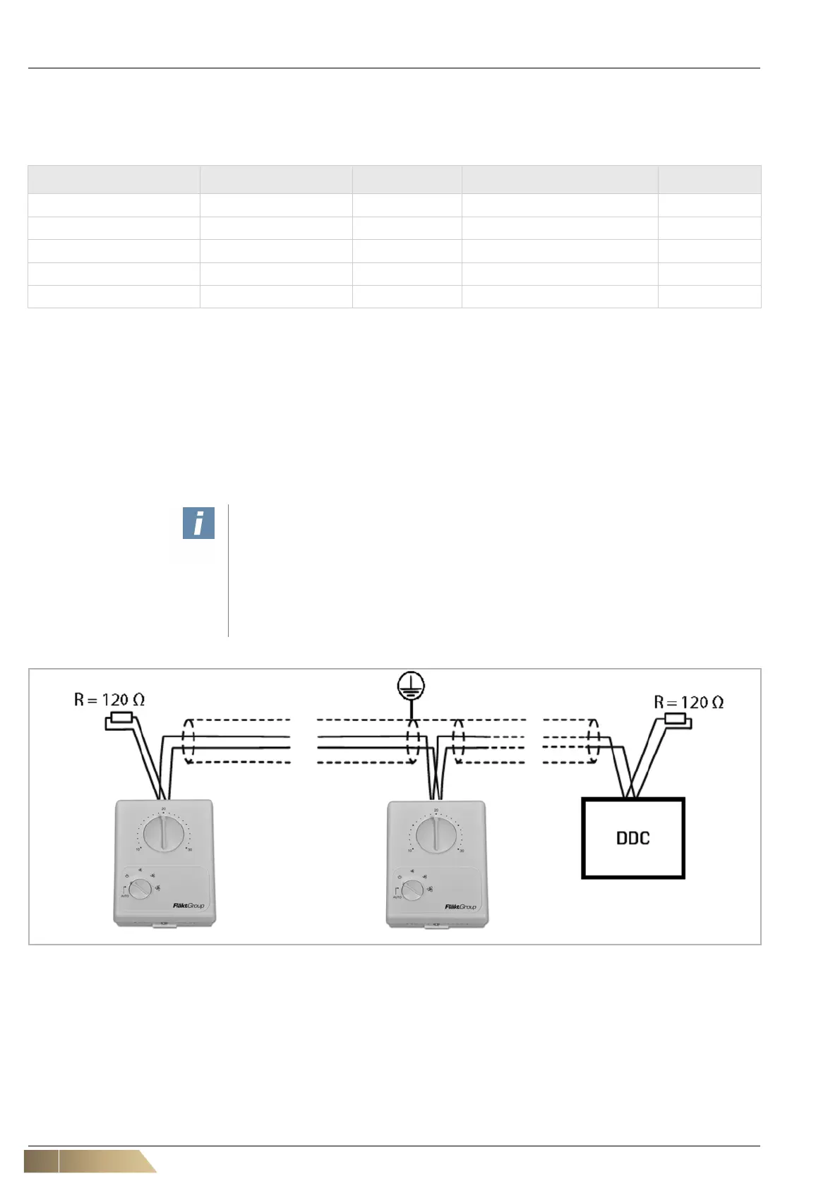
3.3.1 Modbus Network
Fig. 3-1: Modbus Network
Connection type Terminal number Manufacturer Cable type Cross section
AC fan, valves 3,4,5,6,7,8 LAPP cable
ÖLFLEX® CLASSIC 110
1.5 mm
2
Fan EC (0-10V) 9.10 LAPP cable
ÖLFLEX® CLASSIC 110 CY
0.75 mm
2
Status signals 13,14,15,16 LAPP cable
ÖLFLEX® CLASSIC 110
0.75 mm
2
Sensor inputs 11,12,13 LAPP cable
ÖLFLEX® CLASSIC 110
0.75 mm
2
Modbus interface A,B LAPP cable
UNITRONIC® Li2YCYC TP
0.5 mm
2
NOTICE!
• f the Modbus network is longer than 100 meters, a 120 ? resistance should be
installed at the start and end of the bus. .
• The shielding of cables must be connected to at least one point on the PE
conductor.
• Also note the address setting described in Chapter „Set Modbus address“ on
page 22.


 To Next Page