We reserve the right to change designs and technical specifications of our products.
Manual ENA 7-30
1312
ENG
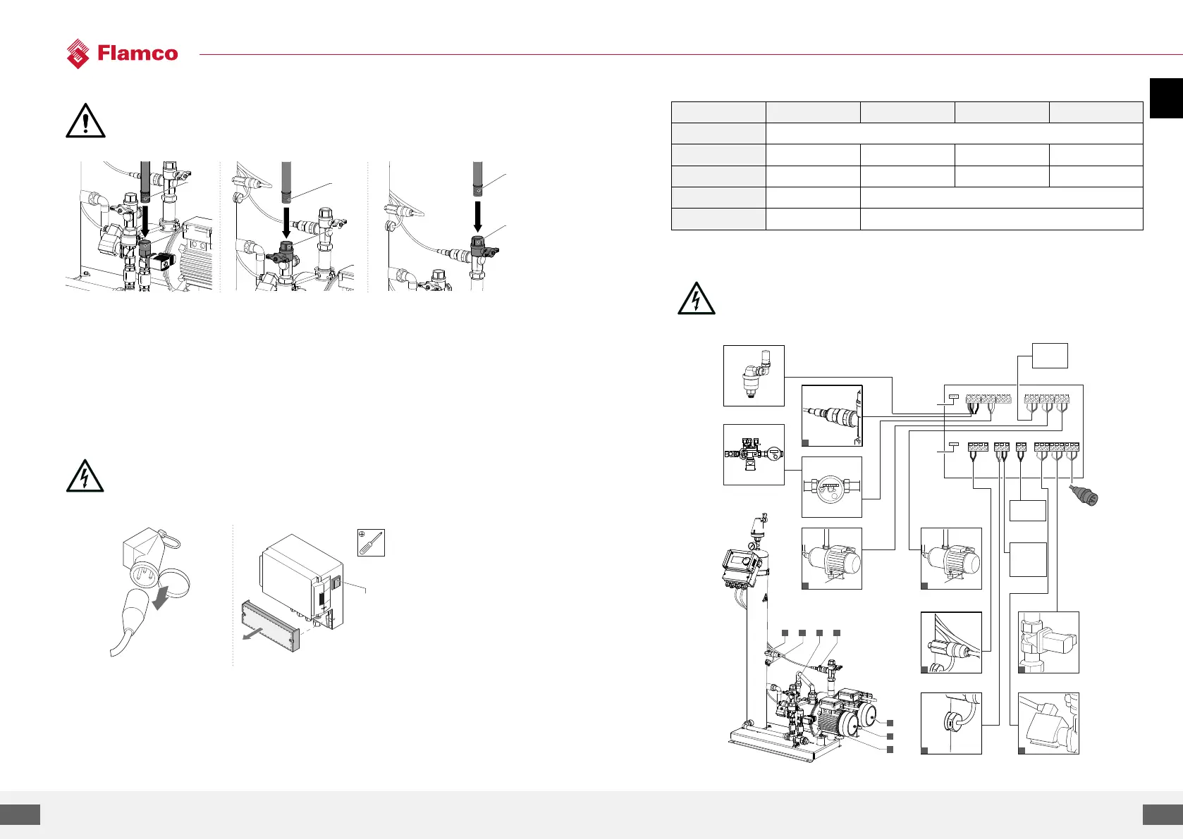
5.3. Hydraulic installation
• Install the shut-o devices on-site in front of the tube joints.
• Only work on non-pressurised and cooled-down pressure joints.
A
B
A
B
A
B
• Connect the supply line
to the refilling supply. If
necessary, install a dirt trap at
the drinking water joint
(0.2 mm).
• Connect the return line of the
system to the inlet of the ENA.
• Connect the supply line of the
system to the pressure side of
the ENA
• The minimum nominal
diameter for the installation
line of the system and the
supply line is DN 20
5.4. Electrical installation
There can be life voltage on the terminal bars even when the main power supply is
disconnected.
Make sure all external power supplies (e.g. external refill equipment) are also
disconnected from the automat.
OFF
Switch o the power switch on the
controller SCU.
Unscrew the protective cover of
the terminal box.
Pull the power plug or switch o
external separators and secure
these against a restart.
The descriptions of the terminal
bars are on the inside of the
protective cover.
5.5. Basic electrical connection
ENA 7 ENA 10
Nominal voltage 230 V: +6%; -10%; 50 Hz: +1%; -1%
Nominal current 2.77 A 5.3 A 7.2 A 10.6 A
Nominal power 0.62 kW 1.1 kW 1.51 kW 2.2 kW
Safety current 10 A 16 A
Protection type IP55 IP54 (pressure sensor IP65)
SELV: Safety Extra Low Voltage
* Recommended value; Line safety switch (C).
Never connect terminal 11+12 and 21+22 at the same time.
It will destruct the refill the SCU controller or the pressure holding control.
28 29 30 31 32 33 34 35 36
27 26 25 24
9 8 7 6 5 4 3 2 1
10 11 12 13 14 15 16 17 18
20 1923 22 21
F
G
D
E
N.C.
N.O.
RS485
RS485
230 V
50 Hz
NFE1.1 / NFE1.2
m
3
L
DBA
E
F
G
C
C
SELV
A
B
Pressure sensor
Impuls Water meter
Pump 1
External
e.g. M-K/U
(Refill 230 V)
INPUT
Pump 2 (ENA 30)
Vacuum pressure switch
Solenoid valve
Solenoid valve
Common
failure
External
refill
(for potential
free contact)
Gas sensor