Do you have a question about the flamco Flamcomat G4 and is the answer not in the manual?
Explains hazard warning symbols used in the manual to ensure user safety.
Defines the manual's scope, intended use, and personnel responsibilities for safe operation.
Specifies necessary qualifications, professional groups, and relevant experience for personnel.
Details training requirements and information transfer for service engineers and contractors.
Describes suitable applications in heating/cooling systems and specific system restrictions.
Outlines procedures for comparing delivered items against the shipping note and inspection.
Provides guidelines for safe transport, warehousing, and unpacking of the equipment.
Defines requirements for the operational environment, including access, floor stability, and atmosphere.
Suggests using insulation for dampening mechanical vibrations and reducing noise from the assembly.
Specifies requirements for emergency stop facilities and safe electrical isolation during installation.
Details mandatory PPE requirements for various tasks to prevent personal injury.
Warns against exceeding pressure/temperature limits, detailing potential consequences and inspection needs.
Defines the required quality of system water and the risks associated with improper media.
Describes built-in safety devices and highlights mechanical and electrical hazards to be aware of.
Warns against applying external forces to the appliance which can cause damage or leaks.
Details inspection requirements, timelines, and procedures according to German ordinance and EU directives.
Recommends periodic inspection of electrical equipment, at least every 18 months.
Outlines safety precautions and procedures for performing maintenance and repairs on the equipment.
Lists examples of obvious misuse that can lead to personal injury or endanger operational safety.
Highlights hazards related to construction part overload and operational continuity under adverse conditions.
Explains the step-by-step process of how the Flamcomat operates in heating/cooling systems.
Details available connectivity ports such as Ethernet, USB, CAN, RS-485, and wireless for system integration.
Describes the information found on the vessel and pump module nameplates, including electrical warnings.
Explains the coding system used for identifying pump control unit models and their specifications.
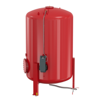
Identifies and describes the various parts of the vessel and its connection assembly.
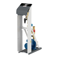
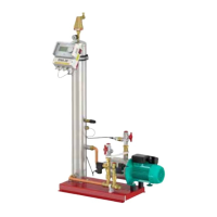
Lists and illustrates the individual components that make up the pump module assembly.
Details the control unit's interface, indicators, buttons, ports, and mounting points.
Provides instructions for fitting the automatic vent, handling the volume sensor, and adjusting the vessel.
Details the hydraulic and electric connections between the vessel, pump module, and control unit.
Explains how to connect the top-up feed, including pressure requirements and backflow prevention.
Describes the need for a drain connection near the unit for safe discharge of system water.
Provides specifications for connecting the unit to the heating or cooling system, including temperature and flow considerations.
Details safety measures, earthing, power supply, and connection procedures for qualified electricians.
Guides through the initial setup, checks, and procedure execution for bringing the unit online.
Explains the icons, names, and functions of the commissioning menu options available on the control unit.
Explains how to set and understand volume levels and operating temperatures for optimal system performance.
Details the meaning and location of various icons used within the control unit's menu interface.
Describes the top-up function and its operation in conjunction with the water treatment module.
Provides a comprehensive list of error codes, their GUI representation, and recommended actions.
Details procedures for restarting the system after long downtimes or power failures.
Provides a step-by-step guide for draining and refilling the main or auxiliary vessels.
Specifies the recommended ambient conditions for storing and operating the equipment.
Illustrates and specifies the minimum clearance distances required for installation around the equipment.
Provides diagrams and notes for common installation scenarios and system configurations.
Presents a table detailing vessel specifications including capacity, dimensions, connections, and deadweight.
Provides a table with dimensions, weights, and connection details for various pump module types.
Lists operational characteristics of the control module, including pressure and temperature limits.
Shows graphs for manual control valve adjustment values based on operating pressure and heating capacity.
Presents a graph illustrating the relationship between flow rate and pressure for top-up functions.
Tabulates nominal electrical values for pump units, including voltage, current, power, fuses, and protection class.
Provides detailed wiring diagrams for Flextronic and Flextronic-400 control units.
| Brand | flamco |
|---|---|
| Model | Flamcomat G4 |
| Category | Water Pump |
| Language | English |