Manual Flamcomat G4 + Flamcomat Starter G4
We reserve the right to change designs and technical specifications of our products.
40
ENG
Installation examples
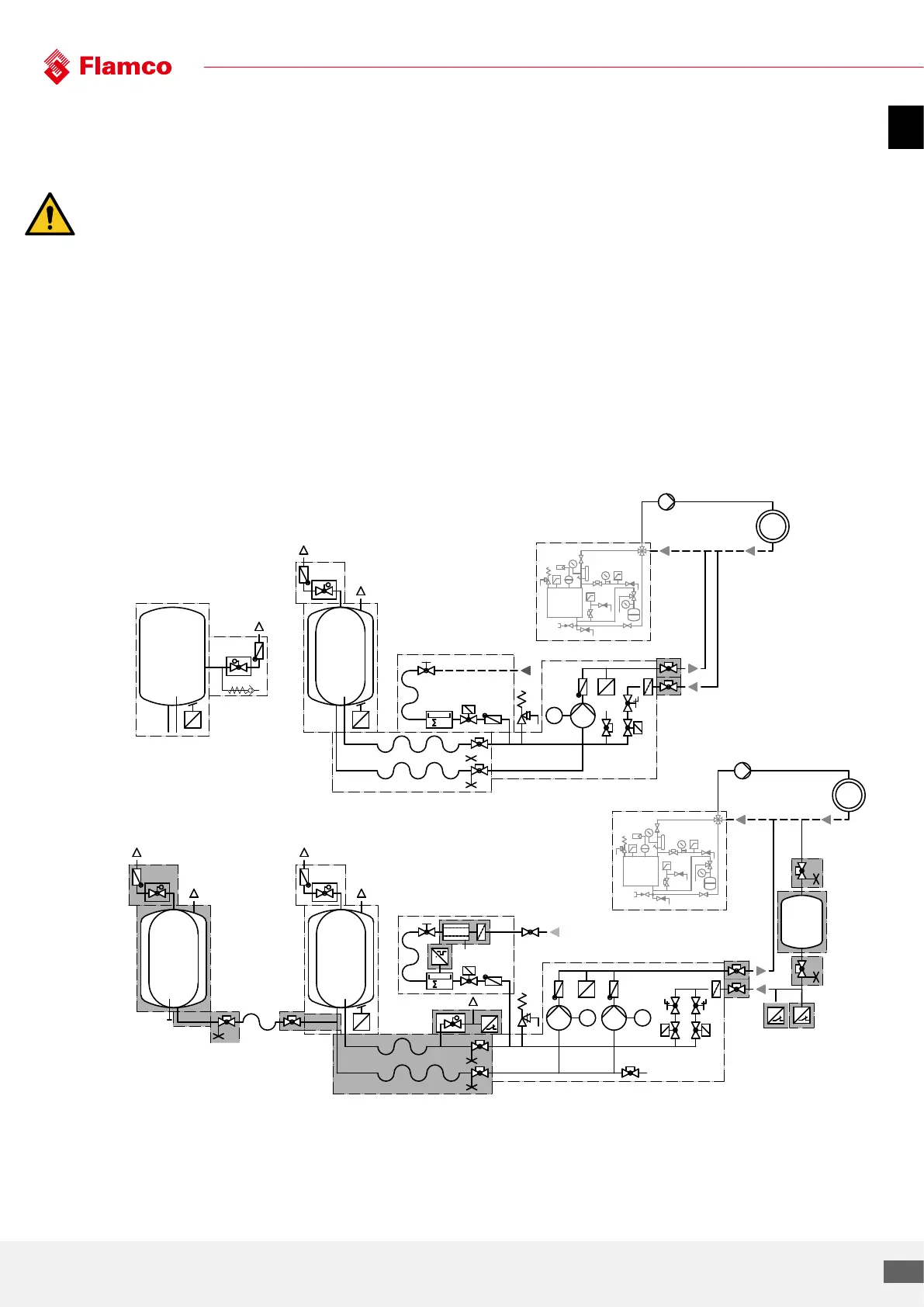
Distance system supply, system discharge, at return integration point, in the range 0.5 ... 1 ... m.
Please note: If the return line is routed horizontally, do not implement the connection from below to avoid
additional contamination with dirt.
1) For design temperatures > 100 °C and > 110 °C, additional requirements from applicable European standards
may apply.
2) Not required acc. to DIN EN 12828
3) Add additional auxiliary vessels symmetrically using a collector line (main vessel at centre) taking into account
minimum distances.
The branch from the main vessel must be flexible.
** accessory, optional extra
P
M1
E
V1
E
F
m
3
V3
T
T
P
P
P
P
M2M1
E
T
V1 V2
m
3
V3
V
E
F
P
T
T
P
P
E
F
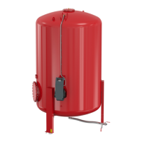
Main vessel
Auxiliary vessel (BB) **3)
Main vessel
System
intake
T-piece G 1 1/2”
vessel branch**
System
output
Lockshield valve
with draining **
Minimum
pressure
limiter **
2
)
Temperature
sensor **
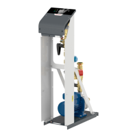
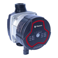
Flamcomat starter
(Top-up feed
non-potable water)
Backflow preventer **
(top-up feed potable water)
Impulse water meter **
Lockshield valve
with draining **
Hose
3)
G 1 1/2”
Supply temperature <= 105 °C
(STB <= 110 °C)
Supply temperature >
105 °C
1)
Return temperature
<= 70 °C
Return temperature
< 70 °C
Heat generator
Lockshield valve **
Heat generator
Control module MP
Control module DP
Sensor connection group **
Flexible connection group
Vessel connector BB **