Manual Flamcomat G4 + Flamcomat Starter G4
We reserve the right to change designs and technical specifications of our products.
24
ENG
• Ensure that no external additional forces can be exerted on the basic vessel (e.g. tools laid on the vessel, things
leaning on the sides).
• Do not fix the basic vessel to the ground on which it is erected (do not use any sort of fastening which can
adversely aect the vessel, e.g. sinking the feet into concrete or lime, welding of the vessel or its feet, clamps
and ties on the body of the structure or appurtenances).
• Place the control module, the basic vessel and the auxiliary vessel at the same height.
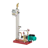
6.2 Vessel connection
The vessel connection is produced as an electric or hydraulic connection to the pump module. For the
installation diagram and example installation see “Appendix 1.” on page 39. Please observe the following
points prior to filling and commissioning of the pressure expansion vessels:
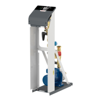
• Install the connection assembly between the vessel and the control module.
Caution: Ensure that the connection between the pump module and the basic vessel is made with the supplied
flexible pressure hoses (connection assembly).
Take note of the labels ‘pump’ and ‘valve’ on the
connections and connect up the appropriate connection
from the pump module (valve) to the pump (valve) on
the vessel connection.
Do not cross these connections and, if necessary, mount
the vessel connection flange so as to enable parallel
pipe fitting. Use the flat seals supplied.
• Connect the signal line via the quick-release connection to the capacity sensor. Screw this connection entirely
into the connector (protection class IP67).
• Open the lockshield valve on the connection assembly between the vessel (basic vessel, intermediate vessel)
and control module.
Valve
Close all valves
Pump
<5m min. DN25
>5m min. DN32
Max length = 20m
(1x 90º Max l = 19m)
(2x 90º Max l = 18m)
<5m min. DN25
>5m min. DN32