Manual Flamcomat G4 + Flamcomat Starter G4
We reserve the right to change designs and technical specifications of our products.
27
ENG
6.6 Electrical Installation
The provision of power supply, (protective) ground wire connection and line protection must be made in
accordance with the regulations of the responsible power company and the applicable standards. The required
information can be found on the type plate of the control unit, the terminal plan (labelling) and in “Appendix 3.”
on page 45.
• All electrical connections should be carried out by a qualified and authorized electrician in accordance with the
latest issue of the IET regulations. The equipment must be earthed. It is strongly recommended that a high-
sensitivity dierential switch (30mA) (residual current device RCD) is fitted on the incoming electrical supply.
• Do not remove covers without first ensuring that the electrical supply is suitably isolated and cannot be
switched on.
• Do not attempt to supply electricity to the equipment unless the protective covers are correctly fitted and held
securely in place.
• Cables connected to the controller volt free contacts may be supplied from another source and may remain live
aer the unit is isolated. These must be isolated elsewhere.
• The user or the installer is responsible for the installation of the correct earthing and protection according to
valid national and local standards. All operations must be carried out by a qualified electrician.
• The Flamco equipment must be connected to a mains isolator switch with a contact gap of at least 3 mm
• It is recommended the switch should be installed within 2m of the equipment.
Hint: install equipotential bonding between earth connection and equipotential bonding conductor. The
minimum diameter, quality and type of the power cables should apply to the on-site applicable rules and
regulations for this application. The electrical control terminals must be connected at the set-up location to
the mains power supply at the relevant operating voltage. The finished system allows the user to program the
configuration and system-dependent parameters into the control unit.
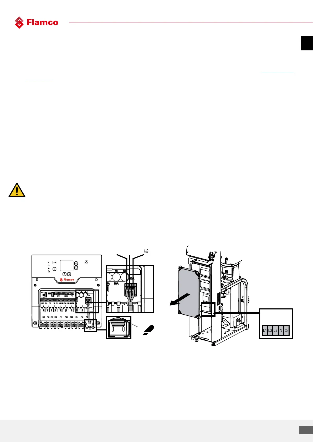
Connect power cable (100 - 240 VAC ~1N PE, 50/60 Hz) Connect power cable (400 VAC ~3N PE, 50/60 Hz)
mm
Projection:
Date:
Revision:
Description:
E
A3
1:5
Project/ECR-nr.:
Date:
EC-description:
Rev.:
L1 L2 L3
N
Mains