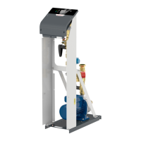
Manual Flamcomat G4 + Flamcomat Starter G4
We reserve the right to change designs and technical specifications of our products.
19
ENG
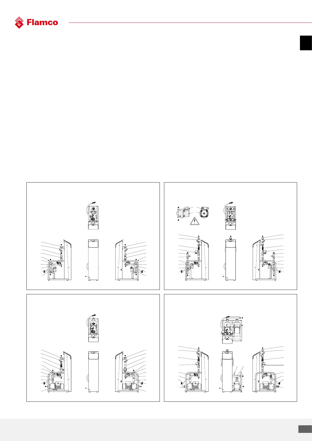
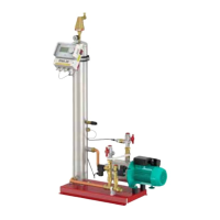
5.6 Component parts, pump module
3 Pump module, control module, including type
plate
3.1 Pump pressure pipe, system supply (marking)
3.2 Pressure sensor
3.3 Pump 1 with manual de-aeration (hex screw with
seal)
3.4 Pump 2 with manual de-aeration (hex screw with
seal)
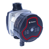
3.5 Pump 1, wet runner, self-priming
A speed select switch, max. position!
B Vent (slotted-head screw with seal)
3.6 Pump 2, wet runner, self-priming
A speed select switch, max. position!
B Vent (slotted-head screw with seal)
3.7 Valve discharge pipe, system discharge (marking)
3.8 Particle filter
3.9 Non-return valve
3.10 Manual regulated valve 1 (diagram)
3.11 Manual regulated valve 2 (diagram)
3.12 Solenoid valve, overflow valve no. 1
3.13 Solenoid valve, overflow valve no. 2
3.14 Top-up line, incorporating the shut-o valve
(lockshield valve), flexible pressure hose,
solenoid valve, top-up vale, no. 3, and check valve
(optional)
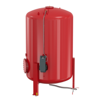
3.16 Safety valve (vessel)
3.17 Lockshield valve system connection (optional)
3.18 Automatic deaerator with air-intake preventer
(MP,DP60-1 -50)
3.19 Control unit, Flextronic
3.20 Bleed pump
3.21 Manual regulated valve 3 (diagram)
3.22 Front panel
3.23 Control unit, Flextronic 400V
MP M-2-50 (MM) DP M-2-50 (DM)
3.3
3.22
3.19
3.14
3.16
3.12
3.10
3.8
3.7
3.9
3.2
3.1
3.3
3.14
3.16
3.12
3.10
3.8
3.7
3.9
3.2
3.1
3.5
3.22
3.19
3.14
3.9
3.16
3.12
3.10
3.8
3.7
3.2
3.1
3.6
3.14
3.9
3.16
3.13
3.11
3.8
3.7
3.2
3.1
A
B
MP M-3-50 (M02) DP M-2-50 (D02)
3.3
3.22
3.19
3.14
3.9
3.16
3.12
3.10
3.8
3.7
3.23
3.2
3.1
3.3
3.14
3.9
3.16
3.12
3.10
3.8
3.7
3.23
3.2
3.1
3.3
3.22
3.19
3.14
3.9
3.16
3.12 3.23.1
3.10
3.8
3.7
3.4
3.14
3.9
3.16
3.13
3.11
3.8
3.7