Manual Flamcomat G4 + Flamcomat Starter G4
We reserve the right to change designs and technical specifications of our products.
22
ENG
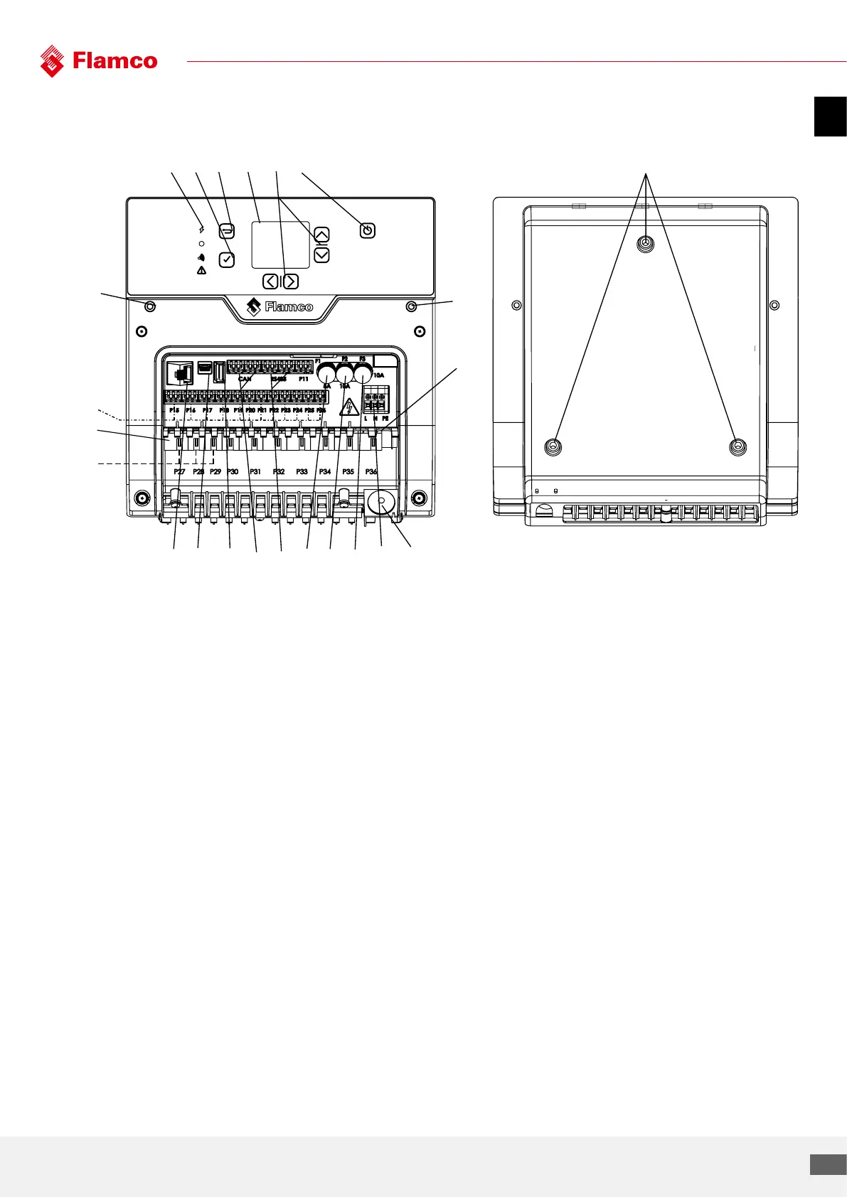
5.7 Control unit
7 8 9 10 11 12 13 14 1615
17
20
1 LED indicator lights
- LED, yellow on: Flextronic is powered.
- LED, Green on: No errors, Automat is running
correctly
- LED, Blue on: Bluetoot is active
- LED, Red on: Error occured.
2 Acceptance button
3 Back button
4 Full color display
5 Navigation buttons
6 ON/OFF button
7 Ethernet port
8 Micro-USB
9 USB
10 CANbus port
11 RS485 port
12 F1, Fuse one (1) 5x20, 5A
13 F2, Fuse two (2) 5x20, 10A
14 F3, Fuse three (3) 5x20, 10A
15 MAINS connection (L, N, PE)
16 MAINS grommet
17 Relay outputs
18 Potential free outputs
19 Sensor and switch inputs/outputs
20 Mounting holes (Flamcomats, Vacumats)
21 Mounting holes (ENA’s, MKU/C’s)