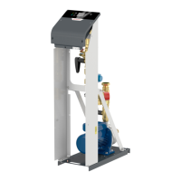
Manual Flamcomat G4 + Flamcomat Starter G4
We reserve the right to change designs and technical specifications of our products.
26
ENG
6.5 System connection
The system connection should be connected to the heating or cooling system.
“Appendix 1.” on page 39 shows the installation diagram and example installation.
Please observe the following specifications before filling and commissioning the pressure-expansion automat:
• The connection should preferably be made in the return line of the heating system. Please note that a
temperature at the system connection > 70 °C (...80 °C) would exceed the permissible pump/diaphragm load
and possibly lead to damage to components. (Complete insulation of the expansion pipe may increase the
temperature load on the control unit and the diaphragm).
• Make sure that this connection is directly connected to the heat generator, and that there are no external
hydraulic pressure influences present at the point of entrainment (e.g. hydraulic balancers, distributors).
• The flow determines how you should install the expansion lines. When fitting expansion lines to the return > 5
m in length, use pipes of at least one nominal diameter larger than that of the pump module. Avoid additional
loads to the system connection of the control unit (e.g. from heat expansion, flow oscillations, dead weights).
• Equipment with flow temperatures > 100 °C must have a minimum pressure limiter fitted in the expansion
line (system drain, valve drain pipework). The arrangement is contained in “Appendix 1.” on page 39. In
applications in accordance with DIN EN12828:2003 (D), this limiter is only envisaged for use if the pressure
holding device does not have an automatic top-up system.
• Use sealants and pipework relevant to the installation; however, please observe at least the maximum
permitted volumetric flow, pressure and temperature values for the expansion line in question (control unit/
system inlet and outlet).
• Fit a non-return valve in the immediate vicinity of the system connection on the control unit that cannot be
unintentionally shut o.
Caution: Close the lockshield valve at the system inlet and outlet of the control unit.