We reserve the right to change designs and technical specifications of our products.
8
3. FlexTherm Eco_A2_ET Controller
3.1 Description
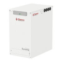
The FlexTherm Eco_A2_ET controller is housed in the unit. The controller parameters can be changed on-site.
The variants of the control boxes available to match the dierent heat storage types as described below.
Figure 3.1: Controller in FlexTherm Eco Units
Power
>50%
>100%
Heating
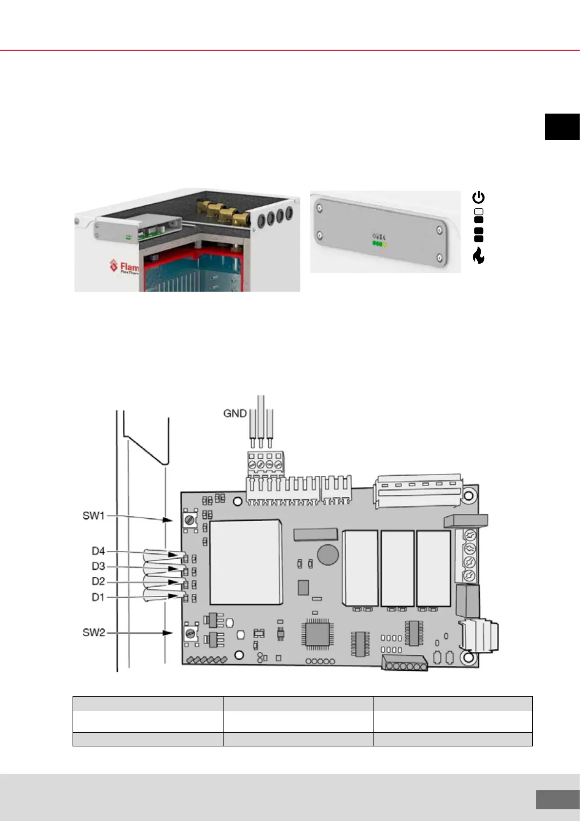
3.2 PCB identification
Location of the switches and LEDs is shown in the figure below. Wiring connections for remote control input are shown, using the 4-way plug in
connector.
Table 3.1: Controller connections
5V input/output 2 J1.6 (FV) Connect to GND for timed boost (user switch)
5V input/output 1 J1.7 (FT) Connect to GND to command element on (PV
inverter)
GND J1.8 (GND) Ground for i/o signals
Remote control input
Boost switch input
ENG