- 12 -
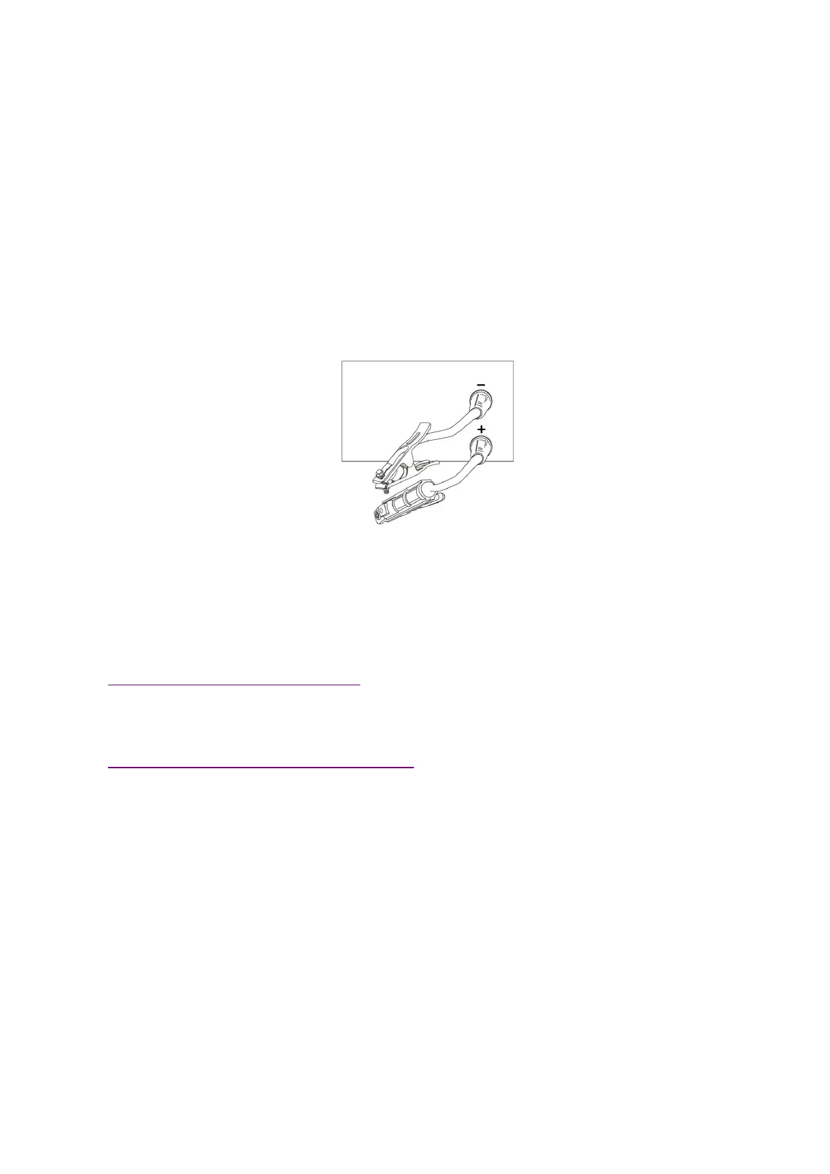
incorrect data adjustment may cause arc instability, spatter and adhesion occur, we can change
the polarity joint for different workpiece as above.
Make sure the cable is connected to the soldering pliers and the quick plug,Connect the quick
plug to the corresponding fast socket
,
And tighten it clockwise. The ground clamp clamps the
workpiece.
When the welding stop, operation [manual welding and gas protection welding switch key],
Manual welding indicator light, into manual welding mode.
In Manual welding mode, adjust
【
Multifunctional data adjusting knob
】
The welding current can be
changed, in
【
Multifunctional data display window
】
display. The welding current range is 30A to
maximum current 150A adjustment.
Operating procedures for MIG
gas protection welding
Welding wire Installation. (Refer to 3.1)
Please choose wire feed roller.V roller for stainless steel and carbon steel.
Connected with The gas cylinder. (Refer to 3.3)
insert the fast plug of the ground wire in the front panel on the fast socket.
Check wire operation
:
press torch switch, the wire feeder will feed the wire through the torch tip.
Select MIG mode on the front control panel(Make sure you are not in SPOOL GUN state). After
that, select the right material and diameter you are welding with. Adjust current according your
workpiece thickness.
To find the best welding performance and suitable for your welding habits. You may also adjust
voltage and inductance to build a perfect welding bead and penetration.