L 10-10 125, L 810, L 1001
52
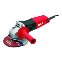
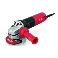
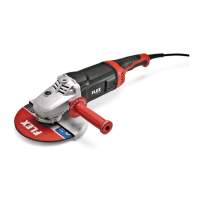
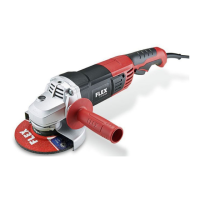
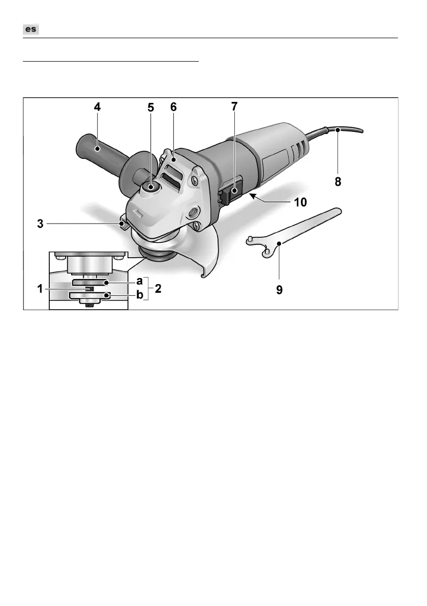
De un vistazo
En estas instrucciones se describen diferentes herramientas eléctricas. La representación
puede diferir en detalles de la herramienta eléctrica adquirida.
1 Husillo
2 Acoplamiento a rosca
a Tuerca de montaje
b Acoplamiento de montaje
3 Cubierta de protección
4 Manija
La manija puede montarse tanto
a la derecha como a la izquierda.
5 Traba para el husillo
Para trabar el husillo durante el cambio
de herramienta.
6 Cabeza del engranaje
Con salida para el aire y flecha
indicadora del sentido de giro.
7 Conmutador balancín
Para el encendido y apagado.
Con traba en una posición, para
el funcionamiento continuo.
8 Cable de conexión a la red de 4,0 m
con el enchufe correspondiente
9 Llave de pivotes
10 Chapa de características (no se
representa)
 Loading...