36
TS 92 18-EC
Remove the arbor nut (G-5) and outer
washer (G-3). Leave the inner washer (G-6)
on the arbor shaft (G-4).
Install the new blade on the arbor shaft
(G-4), making certain the teeth of the blade
are pointing down at the front of the table.
Install the outer washer (G-3) and arbor nut
(G-5).
Lift up the arbor lock lever (G-1), and
securely tighten the arbor nut (G-5)
clockwise.
Turn the saw blade a few times by hand
to see if there is any jamming and confirm
that there is no problem with the rotation
of the saw blade.
Reinstall and secure the table insert.
Attaching the rip fence (see
figure H1-H2)
Ensure that the rip fence lock levers (16) on
both sides of the fence are in the released
position.
Align the notch (H-2) on the rip fence
bracket with one of the 3 index bolts (H-3)
on the front and rear rails.
Ensure that the flip-over fence (H-1) is in its
stored position, facing away from the blade.
Press the lock levers (16) down to secure
the rip fence in place.
Use the flip-over fence (H-1) when cutting
thin workpiece close to the blade.
Storage and transportation (see
figure I1-I11)
Miter gauge storage (see figure I1)
Store the miter gauge under the back side of
the table.
Push stick storage (see figure I2)
Insert the push stick into the push stick holder.
Rip fence storage (see figure I3)
Ensure that the flip-over fence, in its stored
position.
Store the rip fence under the left end of the
table on the rails and latch both of the rip fence
lock levers.
Smart guard system and riving knife
storage (see figure I4)
Slide smart blade guard assembly or riving
knife into holder, then turn lock 1/4 turn to lock
the smart guard system or riving knife in place.
Anti-kickback device storage
(see figure I5)
Slide the anti-kickback device across the
storage bracket and release pawl release button
to lock into place.
Allen key storage (see figure I6)
Store the Allen key under the table. Insert the
long end of the Allen key into the plastic loop
and short end into the storage port.
Blade wrench storage (see figure I6)
Store the blade wrench on the blade wrench
bracket under the table. Slide the blade wrench
onto the threaded rod and install the wing nut
onto the threaded rod, and tighten.
Dust tube (see figure I7)
The dust tube can be stored under the right
side of the table.
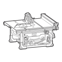
Table saw storage (see figure I8)
Store tool only in orientation, store in other
orientation may lead to tool damage.
Transporting the table saw (see figure I9)
Remove the battery. Store all components and
lower the saw blade.
Lift and carry the table saw by firmly gripping
the two sides of the table.
Mounting the table saw (see figure I10)
The table saw can be mounted securely to a
firm supporting surface such as a workbench,
using the three mounting holes (I-1).
Mounting the table saw to a stand
(see figure I11)
The table saw can be mounted on the FLEX
folding table saw work bench model WB TS
(sold separately).
Adjustments
WARNING!
Remove the battery before carrying out any
work on the power tool.
Adjusting 0°and 45°stops (see
figure J1-J3)
Adjusting 0° stops
Raise the blade to maximum height.
Loosen the bevel lock lever (9) and push
the elevation wheel (8) to the left (0°) or
right (45°) as far as possible, then tighten
the bevel lock lever (9).
Place a combination square on the table
with one end of the square against the
blade. Check to see if the blade is 90° or