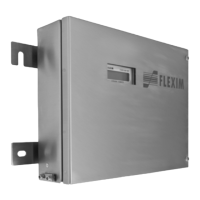
Do you have a question about the Flexim FLUXUS F704**-F2 Series and is the answer not in the manual?
| Measuring Principle | Ultrasonic transit-time difference |
|---|---|
| Flow Velocity Range | 0.01 to 25 m/s |
| Outputs | 4-20 mA, pulse, frequency, relay |
| Power Supply | 24 V DC or 100-240 V AC |
| Inputs | 4-20 mA, RTD |
| Communication | HART, Modbus |
| Degree of protection | IP65 |
| Temperature Range | -40 to +200 °C |
| Pressure Range | Depending on pipe material |
Crucial safety information and warnings for operating the ultrasonic flowmeter.
Important precautions for handling the precision measuring instrument to ensure proper function.
Importance of selecting measuring points away from flow disturbance sources.
Selecting the appropriate location for the measuring point and transmitter.
Procedures for mounting and preparing the ultrasonic transducers.
Instructions for preparing and installing the temperature probe.
Connecting the transducer cables to the transmitter, extension cable, or junction box.
Procedures for connecting the power supply cable to the transmitter.
Connecting external sensors to analog and binary inputs.
Steps for initializing the transmitter to default settings.
Entering essential pipe dimensions like diameter, wall thickness, and material.
Defining medium properties such as sound speed, viscosity, and density.
Adjusting the distance between transducers for optimal measurement.
Initiating the measurement process.
Choosing which physical quantities and units to display.
Setting an upper limit to ignore high flow velocity outliers.
Defining a lower limit below which flow velocities are set to zero.
Using FastFood mode for flows with high dynamics.
Configuring remote functions triggered by binary inputs.
Protecting measurements and settings with a program code.
Adjusting various measurement parameters like damping, cut-off flow, and turbulence mode.
Setting advanced flow parameters like profile bounds and velocity correction.
Diagnosing issues causing measurement impossibility or significant value deviations.
Common problems encountered during measurement and their solutions.
Identifying causes for significant deviations in measured values.


