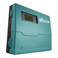
Do you have a question about the Flexim FLUXUS F809 F1 Series and is the answer not in the manual?
General and specific safety warnings for operating the measuring instrument.
Essential handling precautions for a precision measuring instrument to ensure safety and performance.
Explanation of the TransitTime and NoiseTrek measurement principles.
Importance of selecting a measuring point away from flow disturbance sources.
Guidance on choosing measurement arrangements based on range and conditions.
Criteria for selecting the transmitter's location based on measuring point and temperature.
Instructions for wall and pipe installation of the FLUXUS F808 transmitter.
Details on connecting cables to the transmitter terminals for outputs and power supply.
Step-by-step guide for connecting transducer cables to the F808**-A1 transmitter.
Instructions for connecting transducer cables to the F808**-F1 transmitter.
Guide for connecting transducer cables to the F808**-F2 transmitter, including SMB connectors.
Procedures for connecting the power supply to the FLUXUS F808 transmitter.
Information on configuring and connecting transmitter outputs like current loops and binary outputs.
Details on connecting RS232 and RS485 serial interfaces for data communication.
Information on the sensor module's role and installation with the transmitter.
Instructions for wall and pipe installation of the FLUXUS F809 transmitter.
Details on connecting cables to the transmitter for power, outputs, and transducers.
Step-by-step guide for connecting transducer cables to the F809**-A1 transmitter.
Instructions for connecting transducer cables to the F809**-F1 transmitter.
Procedures for connecting the power supply to the FLUXUS F809 transmitter.
Information on configuring and connecting transmitter outputs for FLUXUS F809.
Steps to prepare the pipe surface for transducer mounting, ensuring good acoustic contact.
Guidelines for orienting transducers and setting the correct distance between them.
Guide for entering pipe dimensions and material properties for accurate measurement.
Guide for entering fluid properties like sound speed, viscosity, and density.
Importance and adjustment of transducer distance for optimal measurement.
Overview of data stored in the logger and its activation/settings.
Procedures for transmitting measurement data to a PC via serial interface.
Configuration of various measurement parameters like NoiseTrek, velocity limits, and turbulence mode.
Steps for installing and configuring transmitter outputs.
How to activate and test analog outputs, including setting the output range.
Configuring a frequency output to function as a pulse output for totalization.
Activating a binary output to emit pulses based on totalized physical quantity.
Configuring binary outputs as alarm outputs with customizable conditions and behavior.
Troubleshooting steps for measurement issues like no signal or incorrect values.
Guidance on selecting an appropriate measuring point to avoid issues.
Reasons for large deviations in measured values, such as wrong parameters or gas in the pipe.
| Accuracy | ±0.5% of reading ±0.01 m/s |
|---|---|
| Measurement Range | 0.01 to 25 m/s |
| Temperature Range | -40 to +200°C |
| Fluid Types | Liquids |
| Power Supply | 100 ... 240 VAC or 24 VDC |
| Communication Interfaces | MODBUS RTU |
| Outputs | 4-20 mA, pulse, frequency |


