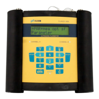
Do you have a question about the Flexim FLUXUS G704 and is the answer not in the manual?
Important safety information including notes, attention points, and directive references.
Guidelines for using the FLUXUS G704 A2 in explosive atmospheres, including connection and housing.
Safety instructions for the junction box JB01S#E3# in explosive atmospheres, covering connections and components.
General precautions for handling the precision instrument, including shock protection and authorized opening.
Explanation of the transit time difference method used for ultrasonic gas flow measurement.
Overview of the flowmeter's keyboard functions, including general functions, navigation, and input.
Importance of selecting a measuring point with adequate straight pipe lengths to ensure a fully developed flow profile.
How reflected pipe wall signals can disturb measurements and points to avoid.
Steps for connecting transducers using the TS system, including direct connection and via junction box.
Instructions for connecting transducers via junction box for ATEX Zone 1 and Zone 2/FM Div. 2.
Procedure for switching on the flowmeter and initial display sequence.
Information on the main menu structure, program branches, and navigation within the display.
Guide for entering outer pipe diameter, pipe wall thickness, material, and lining parameters.
Instructions for selecting and entering medium properties like sound velocity, viscosity, density, and compressibility.
Steps for installing self-adhesive damping mats, including cutting to size and applying to the pipe.
Guidance on recommended transducer distance and initial pipe adjustment.
Procedure for fine-tuning transducer distance based on signal quality and amplitude for optimal measurement.
Instructions on how to interrupt or stop the measurement process.
Guide to selecting measurable quantities like flow velocity, volume, mass, and their units.
How to adjust the display to show two measured values simultaneously.
How to determine heat quantity, total volume, or total mass using totalizers.
Function to automatically set flow velocities below a preset value to zero.
Information on activating/deactivating data memory, setting storage rate, and measuring point identification.
Methods for outputting measured values via serial interface (RS232, RS485).
Setting the ring buffer behavior for handling full data memory, including overwriting or stopping storage.
Details on partitioning the coefficient memory for material properties, medium properties, and coefficients.
Steps to enter material/medium properties as constants, including sound velocity and roughness.
Information on activating and using the extended library for temperature/pressure dependent properties.
Instructions for setting the flowmeter's internal clock for date and time.
Enabling pipe circumference entry as an alternative to pipe diameter in the PARAMETER branch.
Entering temperature correction values for each temperature input.
Setting the time delay for transmitting error values to outputs when valid data is unavailable.
Procedure for activating and deactivating SuperUser mode using HotCodes or by switching off the flowmeter.
Steps to link temperature inputs to measuring channels and activate them.
Activating temperature inputs and other inputs for display, storage, or output.
Steps for installing and activating outputs, including assigning source channel and physical quantity.
Configuring alarm outputs (R1, R2, R3) with switching conditions, holding behavior, and function.
Information on when recalibration is recommended and the process for sending the flowmeter for calibration.
Troubleshooting steps for display issues, checking voltage, and potential component failures.
Guidance on handling the SYSTEM ERROR message, including noting error details and contacting support.
Checks for incorrect parameters, transducer distance, measuring point, and acoustic contact.
Effect of a high cut-off flow setting, zeroing out low flow velocities.
Technical specifications for FLUXUS G704, G704 A2, and G709 flowmeters, including design, measurement, and power.
Technical data for Shear Wave Transducers, including ATEX zone, frequency, pressure, diameter, and temperature ratings.
Overview of menu items within the PARAMETER branch for pipe and medium configuration.
Overview of menu items within the MEASURING branch for channel activation and flow profile correction.
Overview of menu items within the OUTPUT OPTIONS branch for configuring outputs and inputs.
Partitioning the coefficient memory for storing user-defined material and medium properties.
Table of sound velocities for various pipe and lining materials at 20 °C.
| Type | Ultrasonic Flow Meter |
|---|---|
| Measurement Principle | Transit-time difference |
| Fluid Types | Liquids |
| Measurement Rate | Up to 100 Hz |
| Enclosure | IP65 |
| Measurement Range | 0.01 to 25 m/s |
| Pipe Diameter | 6 to 6500 mm |
| Output Signal | 4-20 mA, pulse, frequency |
| Communication Interfaces | RS232, RS485, Modbus |
| Power Supply | 24 VDC |
| Approvals | ATEX, IECEx |
| Temperature Range | -40 to 200 °C |


