UMG70XV3-4EN 12.01.2009 45
6 Installation of FLUXUS G704
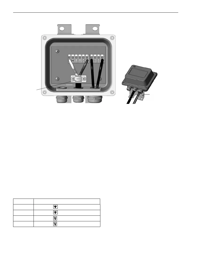
Fig. 6.6: Connection of extension cable and transducer cable (ATEX zone 1)
Connection of the Transducer Cable with the Junction Box
• Remove the blind plug from the junction box (see Fig. 6.5).
• Open the cable gland of the transducer cable. The compression part remains in the
cap nut.
• Push the transducer cable through cap nut, compression part and basic part.
• Prepare the transducer cable with the cable gland. Cut the outer shield and brush it
back.
• Insert the transducer cable in the junction box.
• Tighten the gasket ring side of the basic part in the junction box.
• Fix the cable gland by screwing the cap nut on the basic part.
• Connect the leads to the terminals of the junction box (see Fig. 6.6 and Table 6.4).
Table 6.4: Terminal assignment
terminal connection
V transducer (core)
VS transducer (inner shield)
RS transducer (inner shield)
R transducer (core)
shield terminal
equipotential
bonding terminal
TV TVS TG TG TRS TR V VS RS R