UMG70XV3-4EN 12.01.2009 73
7 Installation of FLUXUS G709
7.8 Connection of the Sensor Module (SENSPROM)
The sensor module contains important transducer data for the operation of the flowmeter
with the transducers. It is connected with the corresponding terminals of the flowmeter.
If transducers are replaced or added, the sensor module has to be replaced or added,
too.
• Disconnect the power supply of the power supply.
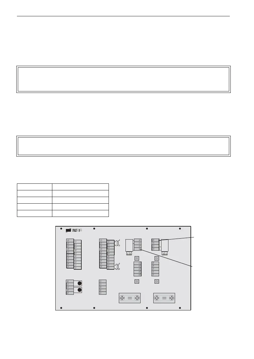
• If the transducer cable has a 4-pole connector, connect it with socket X5 (terminal strip
KL5) or X7 (terminal strip KL7) (see Fig. 7.12).
• Otherwise, connect the sensor module with the terminals of terminal strip KL5 or KL7
(see Fig. 7.12).
• If the cable with the 4-pole connector is cut, it can be connected directly to the terminal
strip KL5 or KL7 (see Fig. 7.12 and Table 7.13).
Fig. 7.12: Connection of the sensor module (SENSPROM)
Note! The serial number of sensor module and transducer have to be iden-
tical. A wrong or incorrectly connected sensor module will result in in-
correct measured values or in measurement failure.
Attention! The sensor module and the connector must not be connected at the
same time.
Table 7.13: Terminals for the connection of the sensor module
terminal connection
SA1 gray
SA2
SA3 brown
SA4 green
T 1 A
T 1 B
P T 1 0 0
T 4 B
T 4 A
P T 1 0 0
B :A :
S A 3
S A 1
S A 2
S A 4
S B 3
S B 1
S B 2
S B 4
A V S
A V
A R S
A G N
A R
B V S
B V
B R S
B G N
B R
A C
2 3 0 V
1 0 0 . . .
D C
V O L T
L O W
4 A +
4 B -
4 2
4 3
4 1
L +
L -
N
L 1
P E
P 4 +
P 5 +
P 2 +
P 3 +
P 1 +
P 6 a
P 7 a
P 7 +
P 5 a
P 6 +
P 4 -
P 5 -
P 2 -
P 3 -
P 1 -
P 6 b
P 7 b
P 7 -
P 5 b
P 6 -
T 2 A
T 2 B
T 1 B
S 1
T 1 A
T 4 A
T 4 B
T 3 B
S 3
T 3 A
T 2 a
T 2 b
T 1 b
S 2
T 1 a
T 4 a
T 4 b
T 3 b
S 4
T 3 a
KL1 KL3 KL5 KL7
KL2 KL4
KL6 KL8
sensor module
measuring
channel A
(KL5)
sensor module
measuring
channel B
(KL7)
X5 X7