Do you have a question about the Flexim FLUXUS G601 and is the answer not in the manual?
Explains the purpose and scope of the user manual.
Highlights important safety notices and symbols used in the manual.
Guides on initial checks and essential care for the precision instrument.
Provides instructions for cleaning and proper storage of the flowmeter.
Explains the clamp-on ultrasonic method used by the flowmeter.
Describes how flow velocity and pipe area are used to calculate volumetric flow rate.
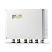
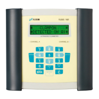
Details the physical components and layout of the transmitter, including the control panel.
Explains LED indicators and where to find the serial number.
Describes the functions of the keys and navigation controls on the transmitter.
Discusses the requirement for the pipe and medium to allow sound signal propagation.
Explains the importance of a developed flow profile and avoiding disturbance sources.
Addresses how pipe wall signals can disturb measurements and points to avoid.
Provides guidance on selecting optimal measuring points considering both profile and noise.
Recommends selecting the measuring point based on chapter 4 and ambient temperature.
Covers placement, hanging, and securing the transmitter onto a pipe.
Details how to connect the transducer cables to the transmitter sockets correctly.
Explains operation using the internal battery or external power supply unit.
Guides on connecting output adapters and wiring for various output types.
Covers connecting temperature probes, current inputs, and using input adapters.
Details how to connect the transmitter to a PC via the RS232 serial interface.
Recommends selecting the measuring point based on chapter 4 and ambient temperature.
Covers placement, hanging, and securing the transmitter onto a pipe.
Details how to connect the transducer cables to the transmitter sockets correctly.
Explains operation using the battery or external power adapter.
Guides on connecting output adapters and wiring for various output types.
Covers connecting temperature probes and using input adapters.
Details how to connect the transmitter to a PC via the RS232 serial interface.
Guides on cleaning and preparing the pipe surface for transducer mounting.
Details the process for mounting both self-adhesive and non-self-adhesive damping mats.
Explains how to position transducers correctly, including arrow orientation.
Details the specific method for mounting transducers using a Variofix rail with chains.
Guides on cleaning the pipe surface for good thermal contact.
Details installation using standard, FLEXIM, or quick-release clasps.
Describes the installation process for probes with an 8-second response time.
Explains how to connect the temperature probe to the transmitter inputs.
Instructions for powering the transmitter on and off using the BRK key.
Explains the main menu, program branches, and navigation methods.
Introduces HotCodes for activating specific settings quickly.
Details how to select the operating language using HotCodes.
Covers entering pipe diameter, thickness, material, lining, and roughness.
Covers entering medium sound speed, viscosity, density, compressibility, temperature, and pressure.
Describes selecting transducer parameters.
Explains how to activate or deactivate measurement channels.
Guides on setting the number of sound paths based on transducer placement.
Covers setting, fine-tuning, and checking transducer distance for optimal signal.
Explains how to start the measurement process and view results.
Describes how to determine flow direction using displayed values and transducer arrows.
Instructions on how to interrupt the measurement using the BRK key.
Guides on selecting the measured quantity and its units.
Explains AutoMux and HumanMux modes for displaying values from multiple channels.
Details how to customize the display for upper and lower lines.
Explains the information shown in the status line for measurement quality.
Shows how to display and check the transducer distance during measurement.
Explains how to adjust the damping factor for stable readings.
Covers totalizer activation, overflow, and storage settings.
How to set an upper limit to ignore invalid flow velocity values.
How to set a lower limit for flow velocity to zero out low values.
Explains how to display flow velocity without profile correction.
Covers enabling, disabling, and configuring storage rate for high dynamic flows.
Details characteristics, parameterization, and output options for calculation channels.
How to adjust the lower limit for inner pipe diameter.
Covers activation, storage rate, settings, measurement, deletion, and memory.
Covers online/offline transmission, formatting, parameters, and data structure.
Explains parameter records for measurement tasks.
Guides on saving current parameters as a record.
Explains how to load saved parameter records.
Instructions on removing stored parameter records.
Describes dividing memory for materials/media.
How to enter properties manually.
Covers introduction, activation, and input of properties using the extended library.
How to remove user-defined entries.
Covers displaying, adding, and removing materials/media from scroll lists.
Instructions for setting the transmitter's internal clock and date.
Covers pipe circumference, medium pressure, point number, transducer distance, temp correction, error delay, alarms, units.
How to activate/deactivate gas measurement and compare sound speed.
How to set standard conditions for gas measurements.
How to adjust the display contrast.
How to view transmitter type, serial number, and memory status.
How to enable/disable SuperUser mode.
How to input transducer parameters in SuperUser mode.
Covers setting profile bounds and applying flow velocity correction.
How to set a limit for signal amplification.
How to set an upper limit for sound speed evaluation.
How to set decimal places for totalizer display.
How to manually reset totalizers.
How to display the sum of totalizers.
What additional info can be displayed.
How to activate the wall thickness measurement mode.
Covers entering pipe material, sound speed, and wall thickness.
Covers performing measurements, checking signal, troubleshooting, and data handling.
How to link temperature inputs to channels.
How to select the type of temperature probe.
How to assign non-temperature inputs.
Covers activating temperature and other input types for measurement.
Explains how to activate and input temperature correction values.
How to install and configure outputs.
How to define the range for analog outputs.
How to define error output behavior.
How to test analog and binary outputs.
How to set delay for error values.
How to activate analog outputs.
How to set measuring range for analog outputs.
How to configure frequency output as pulse.
How to activate binary output as pulse.
Covers activating alarm output, setting properties, limits, and hysteresis.
Covers switching delay, reset, initialization, and state indication during operations.
How to disable configured outputs.
Addresses display failures, system errors, backlight issues, and date/time problems.
Covers issues like no signal, invalid values, poor contact, wrong parameters, and deviations.
Covers totalizer value issues.
Troubleshooting data transmission.
Describes the Parameter branch structure and navigation.
Details input steps for pipe parameters when a channel is selected.
Describes calculation channel selection and configuration.
Describes the Measuring branch structure and navigation.
Describes the Output Options branch structure and navigation.
Describes the alarm output configuration.
Describes the Special Funct. branch structure and navigation.
Describes accessing and navigating System settings.
Describes clock settings.
Describes library management.
Describes material list arrangement.
Describes medium list arrangement.
Describes memory partitioning.
Describes extended library activation.
Covers pipe circumference, medium pressure, point number inputs.
Describes setting sound path input.
Describes setting transducer distance input.
Describes temperature correction activation.
Describes error value delay selection.
Describes alarm state indication activation.
Describes input settings.
Describes measurement settings.
Describes flow velocity display options.
Describes cut-off flow settings.
Describes setting velocity limit.
Describes totalizer overflow activation.
Describes totalizer recall setting.
Describes gas measuring settings.
Describes output settings.
Describes data logger storing settings.
Describes ringbuffer setting.
Describes storage mode.
Describes quantity storage setting.
Describes storing signal amplitude.
Describes storing sound speed.
Describes acoustic signal setting.
Describes serial transmission formatting.
Describes killing spaces.
Describes decimal point setting.
Describes column separation setting.
Describes miscellaneous settings.
Describes contrast setting.
How to view transmitter information.
Describes storing parameter records.
Instructions on removing stored parameter records.
Describes transmitting measured values.
Describes deleting measured values.
Describes battery status display.
Describes input of pipe/lining materials.
Describes editing material properties.
Describes input of media properties.
Describes editing medium properties.
Describes selecting user-defined medium.
Technical data for the FLUXUS G601 transmitter.
Technical data for the FLUXUS G608 transmitter.
Technical data for optional adapters.
Technical data for Shear Wave Transducers.
Technical data for extended temp range Shear Wave Transducers.
Technical data for Lamb Wave Transducers.
Technical data for Shear Wave Transducers (zone 1).
Technical data for Shear Wave Transducers (zone 1, extended temp range).
Technical data for Shear Wave Transducers (zone 2).
Technical data for Shear Wave Transducers (zone 2, extended temp range).
Technical data for Lamb Wave Transducers (zone 1).
Technical data for Shear Wave Transducers (zone 2).
Technical data for Lamb Wave Transducers (zone 1).
Technical data for Lamb Wave Transducers (zone 2).
Technical data for Shear Wave Transducers (zone 2).
Technical data for Lamb Wave Transducers (zone 2).
Guides on selecting appropriate damping mats based on type and pipe dimensions.
Lists measurement units for length, temperature, pressure, density, sound speed, viscosity, and flow.
Table of standard/operational and totalized volumetric flow rate units.
Table of totalized volume units.
Table of mass flow and totalized mass units.
Table of sound speeds for various pipe and lining materials at 20°C.
Table of typical absolute roughness values for different pipe materials and conditions.
Table of properties (sound speed, viscosity, density) for selected media.
Table detailing methane properties at various temperatures and pressures.
Formal declaration that the product meets EC directives and European standards.
| Measurement Principle | Ultrasonic transit-time difference |
|---|---|
| Fluid Types | Liquids |
| Protection Class | IP65 |
| Pipe Diameter Range | 6 to 6500 mm |
| Flow Velocity Range | 0.01 m/s to 25 m/s |
| Accuracy | ± 1.0% of reading |
| Repeatability | 0.15% of reading |
| Power Supply | 100-240 VAC, 24 VDC |
| Outputs | 4-20 mA, pulse, relay |
| Communication Interfaces | Modbus RTU |
| Data Logger | Yes, internal memory |
| Approvals | ATEX |
| Temperature Range (Transducers) | -40…+200 °C (-40…+392 °F) Standard -200…+400 °C (-328…+752 °F) with High Temperature transducers |


