UMG70XV3-4EN 12.01.2009 51
6 Installation of FLUXUS G704
6.6 Connection of the Power Supply
• Prepare the power cable. Connect the leads with the terminals of the power supply
(see Fig. 6.11 and Table 6.10).
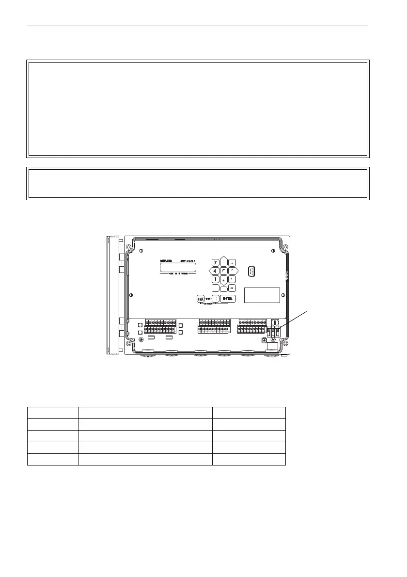
Fig. 6.11: Connection of the power supply
Attention! A switch according to IEC 61010-1:2001 has to be provided in the
building installation which must be near the instrument, easily acces-
sible for the user and marked as disconnection device of the instru-
ment.
If the flowmeter FLUXUS G704 A2 is used in explosive atmosphere,
the switch should be installed outside the explosive atmosphere. If
this is not possible, the switch should be installed in the area with the
least risk.
Attention! The degree of protection of the flowmeter is only guaranteed if the
power cable fits firmly and tightly in the cable gland.
Table 6.10: Terminal assignment (power supply)
terminal connection AC connection DC
PE earth earth
N(-) neutral -DC
L(+) phase 100...240 V AC, 50/60 Hz +DC
fuse 1 A, time-lag 1.6 A, time-lag