UMG70XV3-4EN 12.01.2009 67
7 Installation of FLUXUS G709
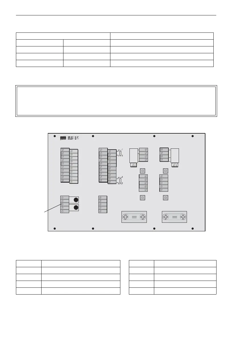
7.4 Connection of the Power Supply
•
Connect the leads with the terminals of terminal strip KL2 (see
Fig. 7.7 and Table 7.8).
Fig. 7.7 : Connection of the power supply
Table 7.7: Terminal assignment
terminal connection
measuring channel A measuring channel B
X6AV X8BV SMB connector (white or marked cable)
X6AR X8BR SMB connector (brown cable)
X5 X7 AMP-Quick connector
Attention! A switch according to IEC 61010-1:2001 has to be provided in the
building installation which must be near the instrument, easily acces-
sible for the user and marked as disconnection device of the instru-
ment.
Table 7.8: Terminal assignment (power supply)
terminal connection AC terminal connection DC
PE earth PE earth
N neutral L- -DC
L1 phase 100...240 V AC, 50/60 Hz L+ +DC
fuse 1 A, time-lag fuse 1.6 A, time-lag
T 1 A
T 1 B
P T 1 0 0
T 4 B
T 4 A
P T 1 0 0
B :A :
S A 3
S A 1
S A 2
S A 4
S B 3
S B 1
S B 2
S B 4
A V S
A V
A R S
A G N
A R
B V S
B V
B R S
B G N
B R
A C
2 3 0 V
1 0 0 . . .
D C
V O L T
L O W
4 A +
4 B -
4 2
4 3
4 1
L +
L -
N
L 1
P E
P 4 +
P 5 +
P 2 +
P 3 +
P 1 +
P 6 a
P 7 a
P 7 +
P 5 a
P 6 +
P 4 -
P 5 -
P 2 -
P 3 -
P 1 -
P 6 b
P 7 b
P 7 -
P 5 b
P 6 -
T 2 A
T 2 B
T 1 B
S 1
T 1 A
T 4 A
T 4 B
T 3 B
S 3
T 3 A
T 2 a
T 2 b
T 1 b
S 2
T 1 a
T 4 a
T 4 b
T 3 b
S 4
T 3 a
KL1 KL3 KL5 KL7
KL2 KL4
KL6 KL8
power supply
(KL2)